Inst ToolsInst ToolsInst Tools
  • Courses
  • Automation
    • PLC
    • Control System
    • Safety System
    • Communication
    • Fire & Gas System
  • Instrumentation
    • Design
    • Pressure
    • Temperature
    • Flow
    • Level
    • Vibration
    • Analyzer
    • Control Valve
    • Switch
    • Calibration
    • Erection & Commissioning
  • Interview
    • Instrumentation
    • Electrical
    • Electronics
    • Practical
  • Q&A
    • Instrumentation
    • Control System
    • Electrical
    • Electronics
    • Analog Electronics
    • Digital Electronics
    • Power Electronics
    • Microprocessor
  • Request
Search
  • Books
  • Software
  • Projects
  • Process
  • Tools
  • Basics
  • Formula
  • Power Plant
  • Root Cause Analysis
  • Electrical Basics
  • Animation
  • Standards
  • 4-20 mA Course
  • Siemens PLC Course
Reading: Root Cause Analysis for Tank Overflow due to Valve Problem
Share
Notification Show More
Font ResizerAa
Inst ToolsInst Tools
Font ResizerAa
  • Courses
  • Design
  • PLC
  • Interview
  • Control System
Search
  • Courses
  • Automation
    • PLC
    • Control System
    • Safety System
    • Communication
    • Fire & Gas System
  • Instrumentation
    • Design
    • Pressure
    • Temperature
    • Flow
    • Level
    • Vibration
    • Analyzer
    • Control Valve
    • Switch
    • Calibration
    • Erection & Commissioning
  • Interview
    • Instrumentation
    • Electrical
    • Electronics
    • Practical
  • Q&A
    • Instrumentation
    • Control System
    • Electrical
    • Electronics
    • Analog Electronics
    • Digital Electronics
    • Power Electronics
    • Microprocessor
  • Request
Follow US
All rights reserved. Reproduction in whole or in part without written permission is prohibited.
Inst Tools > Blog > Root Cause Analysis (RCA) > Root Cause Analysis for Tank Overflow due to Valve Problem

Root Cause Analysis for Tank Overflow due to Valve Problem

Here we will discuss the root cause analysis of an incident in which a tank filled with water started overflowing due to a valve problem.

Last updated: September 28, 2022 4:47 pm
Editorial Staff
Root Cause Analysis (RCA) Control Valves
No Comments
Share
5 Min Read
SHARE

Today in this article we will discuss about the root cause analysis of an incident in which a tank filled with water started overflowing.

Contents
Problem StatementRoot Cause Analysis for Valve Problem

The incident had occurred in a tank in which water was filled. If the tank had some other hazardous liquid, then this could have created fatality.

Root Cause Analysis for Valve Problem

Problem Statement

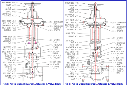
A tank was installed in one of the plants in a refinery for storing the water in it. The feed inlet of the tank was controlled using an On-Off valve (butterfly body & rack and pinion actuator). The fail action of the On-Off valve was fail-close.

One day, the field operator informed us that the valve is having some leakage from the actuator side. The instrumentation team checked the valve and found that the actuator of the valve is passing. So, actuator overhauling was needed.

On the next day, the actuator was dropped for overhauling purposes. But the operation requirement was to have the valve in an open condition as the tank was having a low level. Tank filling was in-progress.

So, in valve open condition, the actuator was dropped by giving external air to the actuator to keep the actuator open. After overhauling the actuator, the actuator was reinstalled. The actuator was reinstalled in another shift by a different person.

After a few hours, during the field round, the field operator observed that the tank was overflowing. Immediately the tank inlet was isolated.

When the actuator was reinstalled after the maintenance job, the tank level was 82%. Above 80%, the tank feed inlet valve is in close condition. When the level goes below 25%, the feed inlet valve opens again.

Root Cause Analysis for Valve Problem

So, what can be the probable reason for tank overflow?

Probable Problem 1: The level transmitter showed a low value while the actual level was high.

The level transmitter was working ok. When the tank started overflowing, the level transmitter was showing 101%. The same level was confirmed with the level gauge.

Probable Problem 2: On-Off valve did not close when the level was above 80%.

The feedback from the On-Off valve was close feedback.

Probable Problem 3: The proximity switch malfunctioned and started showing close feedback when the valve was open.

The proximity switch’s functionality was checked. Found ok.

Probable Problem 4: Passing from the On-Off valve body

This might be the probable reason.

Probable Problem 5: Passing problem in bypass valve given for feed inlet valve.

When the isolation valve for the On-Off valve was closed, the tank’s overflow stopped. Hence there was no issue with the bypass line valve.

Probable Problem 6: The actuator direction was incorrect during installation

This can also be one of the reasons.

Observations after taking the On-Off valve for maintenance:

  1. The actuator was dropped for further checking purposes. The valve was in close condition while dropping the actuator.
  2. While dropping the body for checking the passing issue, the body was found in open condition.

This means that the actuator’s direction of installation was incorrect.

What went wrong?

During the job, the actuator was dropped in open condition. While reinstalling the actuator, the technician installed the actuator in close condition, while the body was in open condition.

The technician was unaware of this because the body had a coupler of square shape. The technician did not check the condition of the body by removing the coupler.

The technician installed the actuator in close condition. Then he set the feedback and handover the valve for operation.

The direction of every instrument before removing should be marked as well as the proper handover of jobs should be given.

Don't Miss Our Updates
Be the first to get exclusive content straight to your email.
We promise not to spam you. You can unsubscribe at any time.
Invalid email address
You've successfully subscribed !

Continue Reading

Solenoid Valves Practical Problems
18 Temperature Sensors Fault Leads to Plant Shutdown
Self Actuated Pressure Control Valve Principle
Globe Valve Body Design
Control Valve Positioners
Locked Open (LO) and Locked Closed (LC) Valves
Share This Article
Facebook Whatsapp Whatsapp LinkedIn Copy Link
Share
Leave a Comment

Leave a Reply Cancel reply

Your email address will not be published. Required fields are marked *

Stay Connected

128.3kFollowersLike
69.1kFollowersFollow
210kSubscribersSubscribe
38kFollowersFollow

Categories

Explore More

Failing Weigh Feeders and Mechanical Variable Speed Drives (VSD)
Free Control Valves Course
Gearbox within week Failing Journal Bearing upset Plant Operations
Control Valve Flow Direction
Valve Basics, Sizing, and Actuators Books
What is Cage-guided Globe Valve ?
What is a Hydraulic Valve? and their Types
Root Cause Analysis – Burst Transformers and 11 kV Input Breakers

Keep Learning

Electrical Engineering Problems - Root Cause Analysis

30 Electrical Engineering Problems – Root Cause Analysis

Control Valve Tips and Tricks

Control Valve Tips and Tricks

Basic Configuration of Motor Operated Valve

Rotork Motor Operated Valve Basic Configuration

Mechanical Temperature Indicators (MTI) Problem

Mechanical Temperature Indicators (MTI) Problem

Gas Valve Sizing

Gas Valve Sizing

Air Release Valve

What is an Air Valve? Purpose, Types, Advantages, Disadvantages

CO2 Stripper Old Differential Pressure Transmitter Stopped Working

CO2 Stripper Old Differential Pressure Transmitter Stopped Working

Control Valve Plug Stem and Gland Leaks

Repeat Control Valve Plug Stem and Gland Leaks

Learn More

Electrical Conduit Seal

Assembling an Electrical Conduit Seal

Safety Instrumented System Engineer Interview Questions

Safety Instrumented Systems Online Exam

Control Systems Questions & Answers

Control Systems Objective Questions & Answers – Set 8

Door Locking System - PLC Applications Examples

Door Locking System – PLC Applications Examples

Measurement of Phase Angle Objective Questions

Measurement of Phase Angle Objective Questions

Pressure Gauge Maintenance and Troubleshooting

Pressure Gauge Maintenance and Troubleshooting

Digital Electronics Multiple Choice Questions

Demultiplexers Objective Questions

Simulating Level Sensor and the Pump Logic in PLC

PLC Basics – Manual Control, Closed Loop, ON-OFF with Hysteresis

Menu

  • About
  • Privacy Policy
  • Copyright

Quick Links

  • Learn PLC
  • Helping Hand
  • Part Time Job

YouTube Subscribe

Follow US
All rights reserved. Reproduction in whole or in part without written permission is prohibited.
Welcome Back!

Sign in to your account

Username or Email Address
Password

Lost your password?