In this post, we will see how to configure PID controller in various Schneider PLCs (programmable logic controller)
PID configuration differs in various PLCs. In this post, we will see its configuration in Schneider PLC’s.
Schneider PLC PID Controller
Basically, we will cover three types of PLC software in Schneider
- Machine Expert Basic
- Machine Expert, and
- Control Expert
Let us have a detailed look at this three software.
Machine Expert Basic
Refer to the below images by step. We will configure a simple PID here and not go into advanced types.
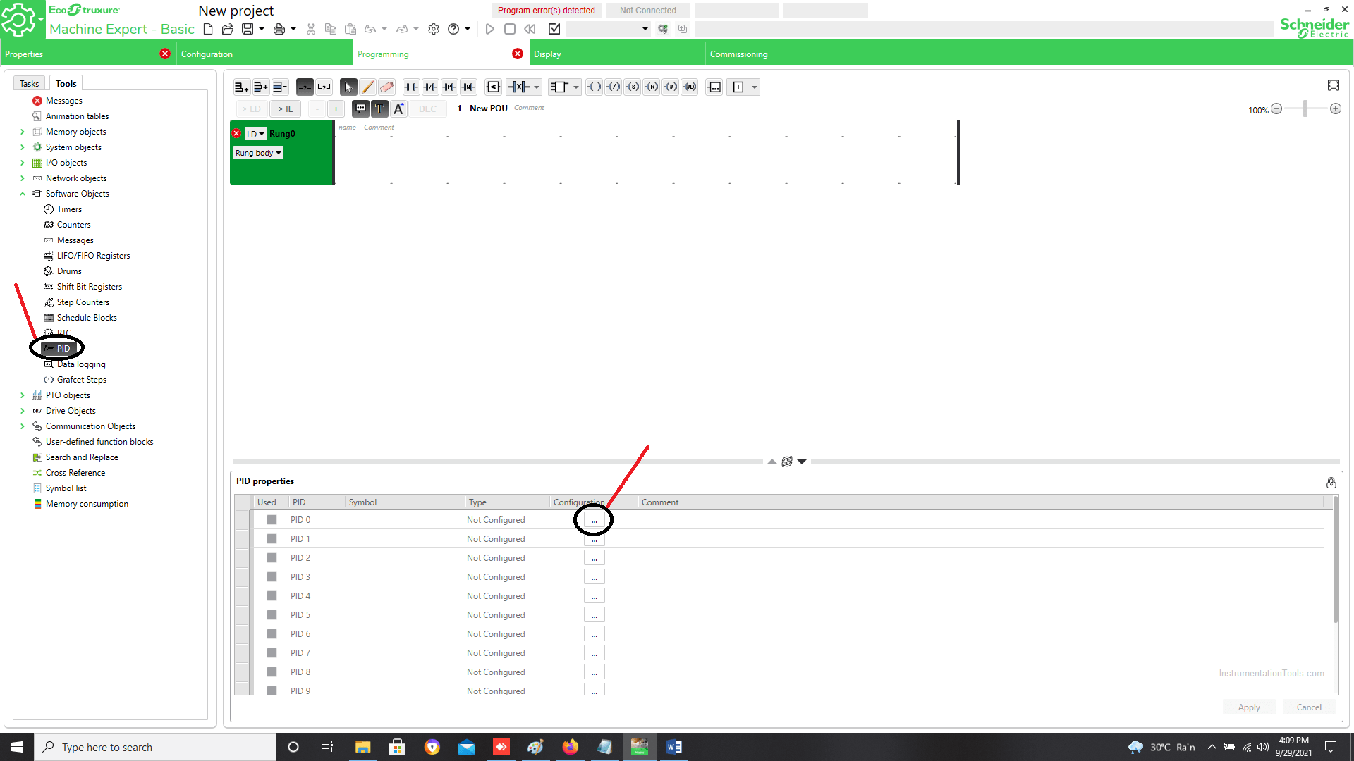
In the first image, as shown, click the PID tab in the Tools tab. A dialog window will open at the bottom.
Click the square symbol in the configuration menu as shown.
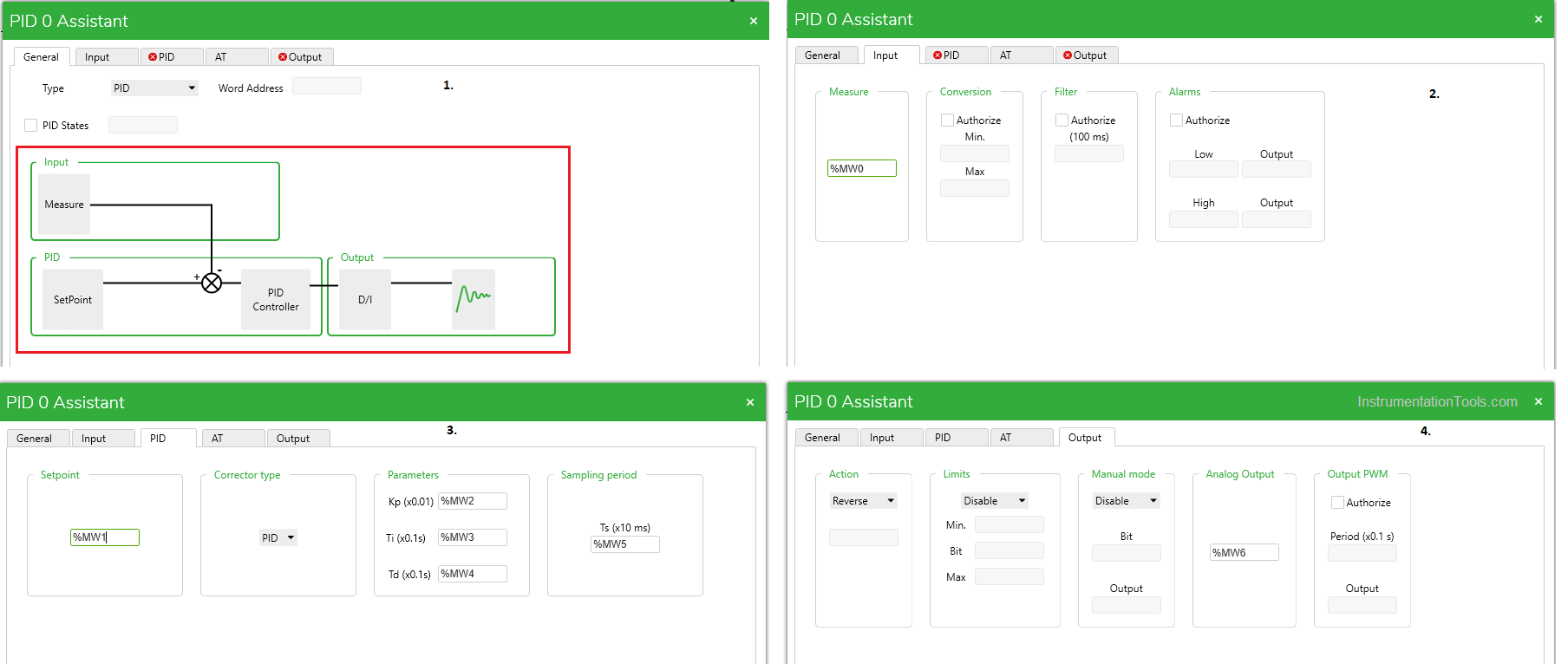
In the second image, as shown, after clicking the square symbol, a popup window will appear as shown. In the window, there are five tabs – General, Input, PID, AT, and Output.
In the General tab, select the type of action. In the Input tab, enter a memory address in the Measure tab. This is nothing but the process variable which is to be controlled.
In the PID tab, enter the memory addresses for set-point, Kp (P), Ti (I), Td (D), and Ts (Sampling Period). Also, select the corrector type.
In the Output tab, enter the memory address for analog output. This is the output of PID.
Also, select the action type, select whether you need to enable or disable the output limits and select whether you need to enable or disable manual mode.
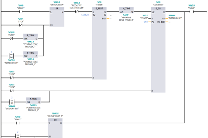
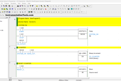
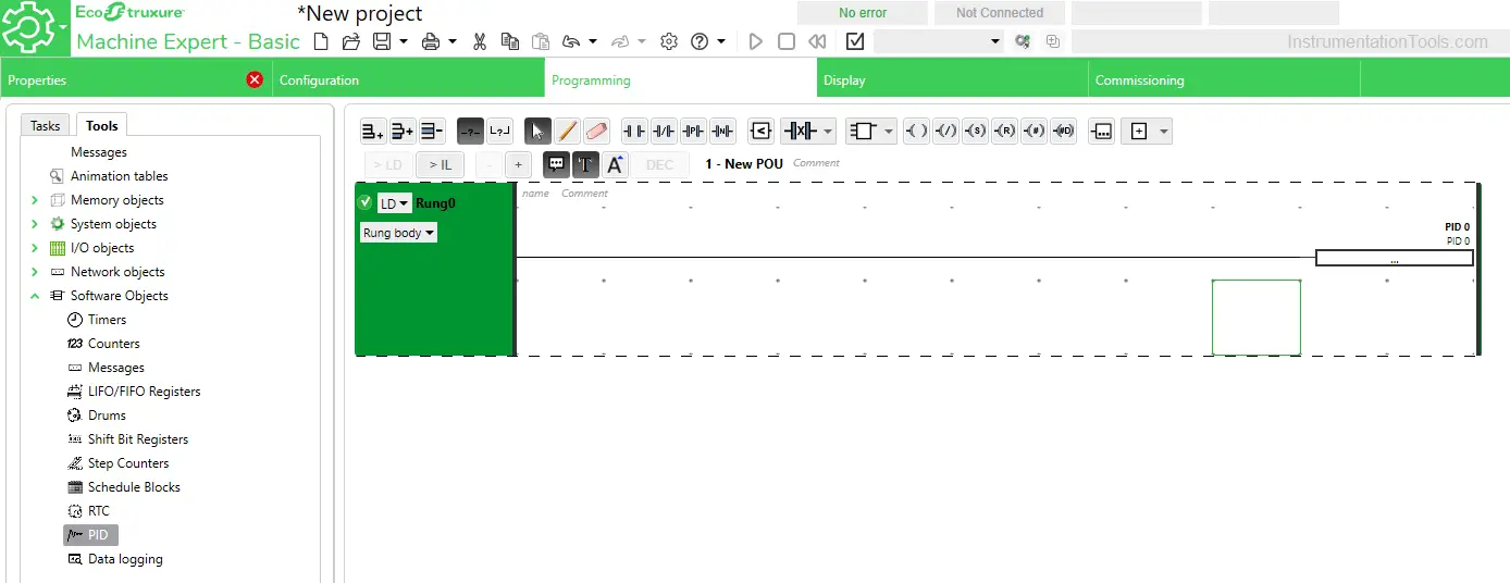
In the third image, as shown, write a rung as shown. This needs to be written to enable the PID logic. If this rung is not written, then that particular PID will not be enabled.
The memory addresses that you defined in the PID block must be configured in an external HMI also. This is required for allowing the operator to set the required parameters directly from HMI.
Once you have configured the PID, you can check it by downloading it in PLC. Remember that it does not work in simulation mode. You need to physically connect a PLC.
Depending on the set parameters and the process variable, you will directly get the PID output in the memory address that you had defined in the analog output tab.
Machine Expert
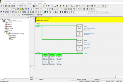
In this software, it is relatively easier to configure PID. You need to take a PID block from the library in the section you are writing. Then, assign addresses to the input pins as shown in the figure.
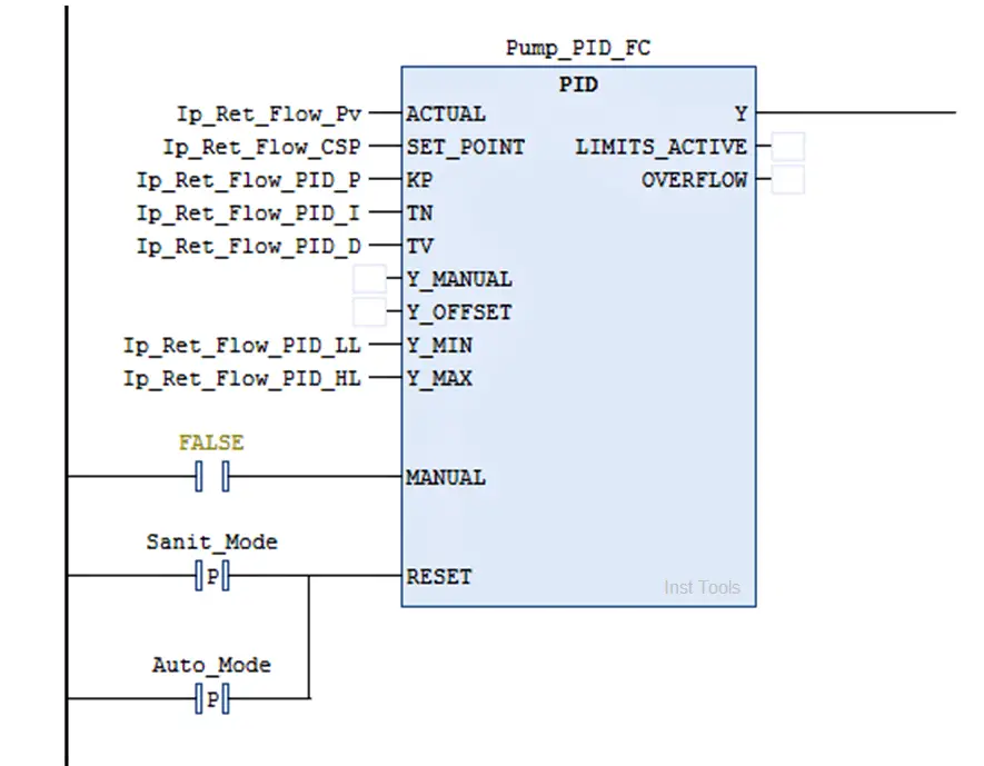
It would be better if you assign Kp (P) and Tn (I) as real type variables. The more accurate you set in decimals, the more accurate will be the output.
The remaining variables can be assigned as integer-type variables. If you require manual mode, then you just need to enable it by assigning a variable in manual input and assigning a manual set-point in Y_MANUAL input.
You can reset the PID if you need it by assigning a variable as shown. The PID function will be reset and the output will be given in a fresh way.
Unity Pro
In this software, it is relatively easier to configure PID. You need to take a PID block from the library in the section you are writing.
Then, assign addresses to the input pins as shown in the figure. Here, there are two inputs that are different as referred to what we saw earlier – Mode and Para.
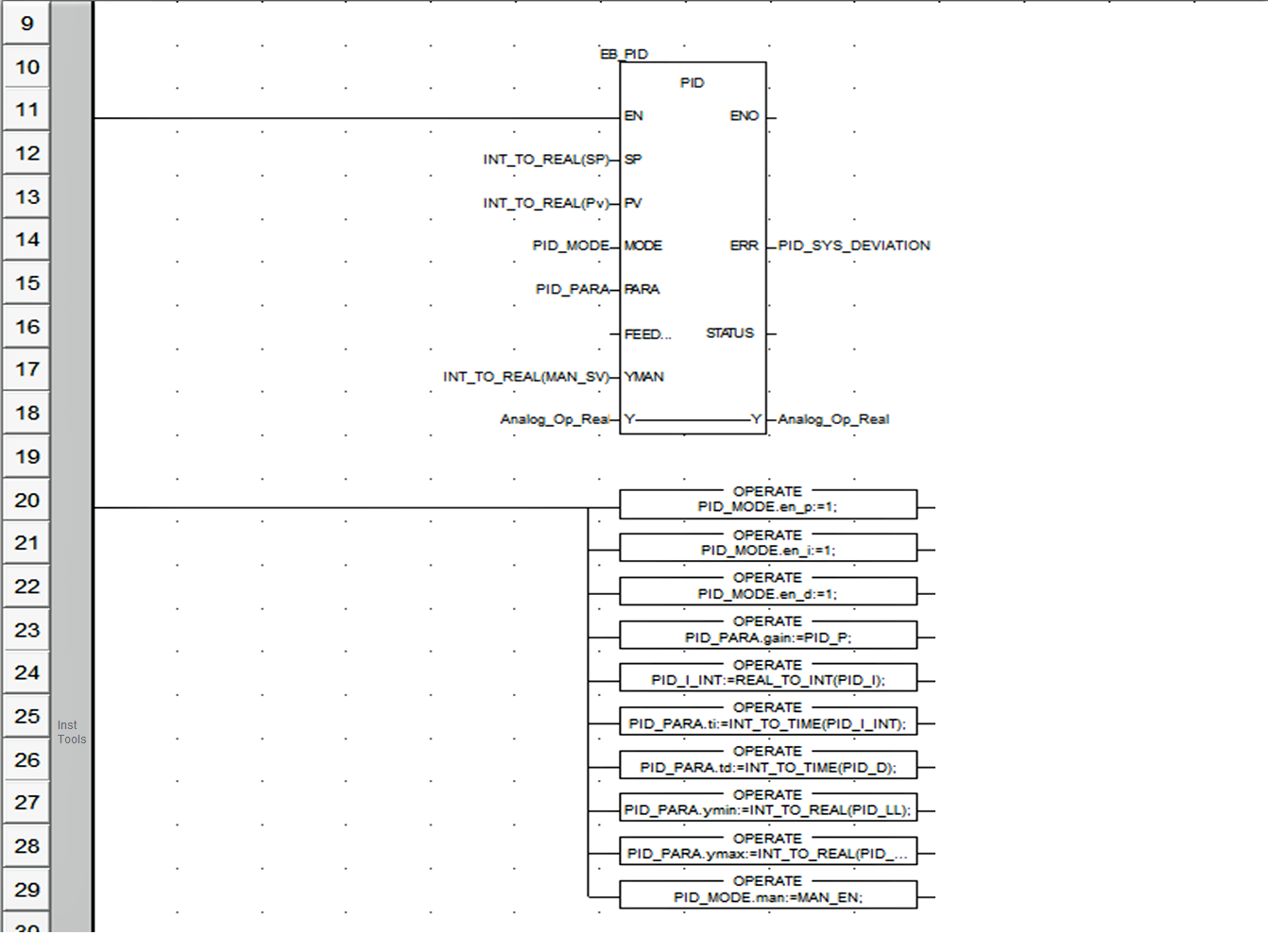
Basically, they both are structure variables. You have to assign values to each element of the structure as shown in the above figure.
In this way, we got to know how to configure PIDs in all three different types of software.
If you liked this article, then please subscribe to our YouTube Channel for Instrumentation, Electrical, PLC, and SCADA video tutorials.
You can also follow us on Facebook and Twitter to receive daily updates.
Read Next:
- DCS Troubleshooting
- Commissioning of DCS System
- DCS Control System Spares
- Yokogawa DCS Architecture
- DCS System Layout