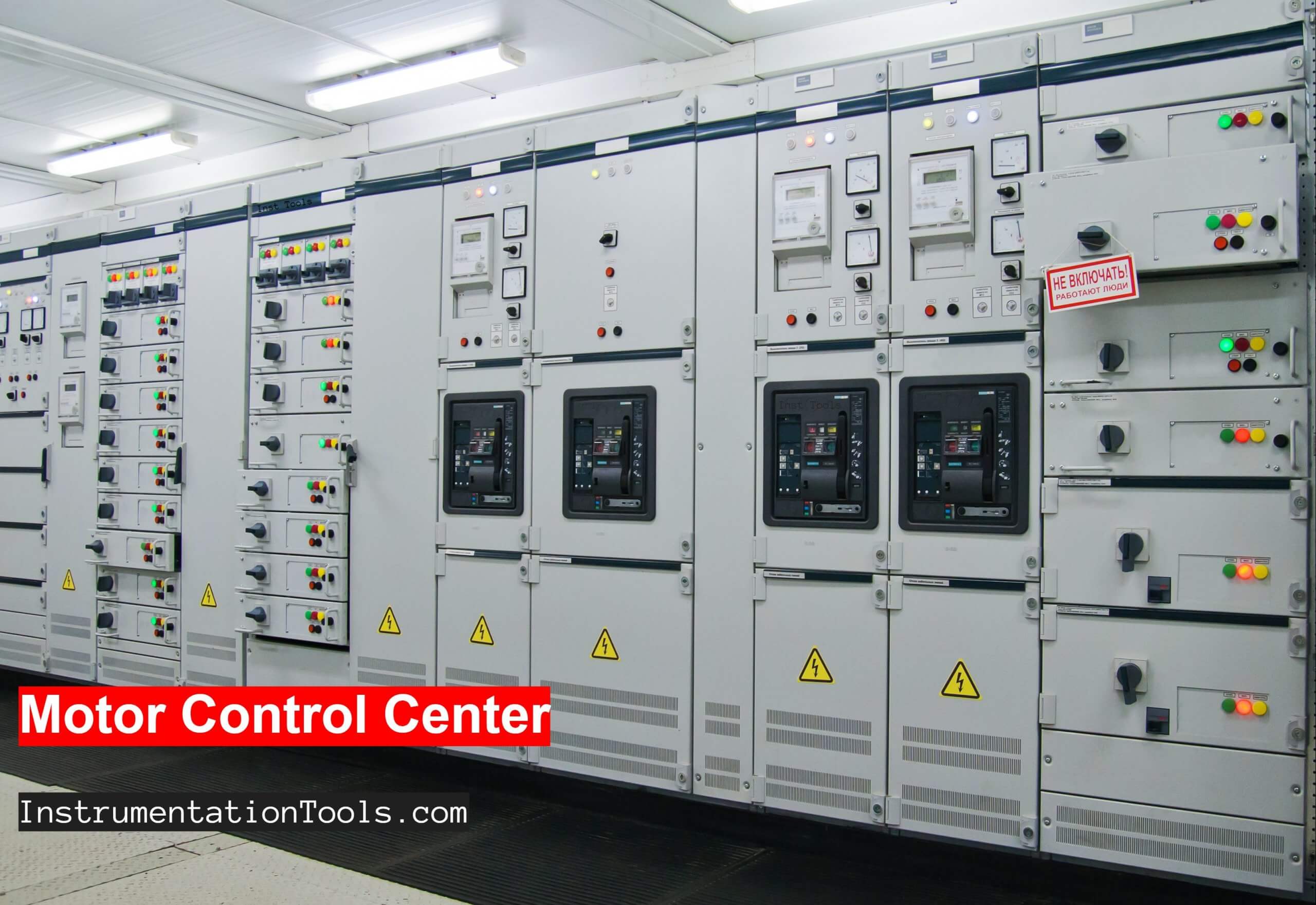
A Motor Control Center (MCC) comprises metal enclosure panels that feed, control, and protect circuits. Load distribution consists of motors and that use contactors or starters as the main control components.
MCCs are provided with Class I or Class II wiring. With any of the classes, the user can specify the physical arrangement of the units within the motor control center (subject to design parameters).
Purpose of Motor Control Center
MCCs are used as a link between generation equipment and end consumers such as engines, air conditioning equipment, etc.
The MCCs offer the advantage of integrating within the same cabinet the motor starter systems of different areas of a plant as well as the distribution system of the same.
When using this equipment costs are reduced since the power lines reach a single place (the MCC). From MCC the power and control cables go to the final loads.
Starters
Starters are the simplest control devices that can be used to start motors and to protect them against overloads.
There are several types of starters on the market. Very few are discussed in this article.
• Non-Reversible Full Voltage Magnetic Starters.
Full voltage starters are the simplest control devices that can be used to start motors and to protect them against overloads.
They can be used when the starting current of the motor does not have a high value for the line feeding the motor and when the starting torque under these conditions is not detrimental to the machine driven by the motor.
• Reversible Full Tension Magnetic Starters.
These starters are designed to operate AC motors in both directions, connect the motor directly to the line, and can be used when the motor starting torque is not too high for the line.
It consists of a mechanical-electrical interlock that prevents the contactors from closing simultaneously.
• Electronic Soft Starters.
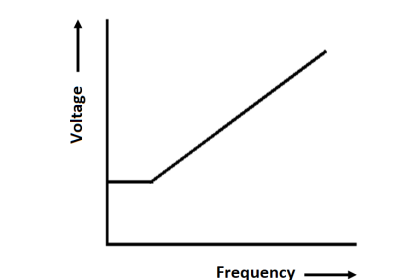
This type of starter uses an electronic technique to first generate a current-limiting soft start. This is achieved by reducing the voltage at the motor terminals, which also reduces the torque and consequently the starting current; the result: a soft start, without vibrations and therefore without wear, which also corrects the power factor.
Soft start is achieved by varying the voltage across the motor terminals, creating a voltage ramp. The starter is equipped with a microprocessor governed phase-cut control for soft start. Employing this control, only the motor voltage is varied; the frequency is and always corresponds to that of the network.
The number of sections in a motor control center depends on the space taken by each of its components, so if the designer knows which components will be included, the motor control center can be designed.
MCC wiring Classification
The following are various NEMA classifications and their description. Wiring of MCC conforms to two NEMA classes (1, and 2) and three types (A, B, C).
Class 1
Contactors, overload relays, protective devices, and bus bar systems are arranged conveniently. But provides no wiring or interlocking between the units by the manufacturer.
The manufacturer provides only drawing of compartments but no wiring between the compartments of the center. Class 1 type MCCs are recommended for small projects, where a limited number of motors are involved.
Class 2
Required to providing by the manufacturer, with interlocking and their control wiring completed between compartments of the center.
With Type A: No terminal blocks (TBs) are provided.
With Type B: All connections within individual compartments are made to the terminal blocks.
With Type C: All connections are made to the master terminal block located in the horizontal wiring through at the top bottom of the center.
MCC Selection Classification
MCC selection is based broadly on the adoption of Network Technology, Structure, Power systems, Unit design, and Unit types.
Networking
MCCs can be connected by the utilization of the latest network technology such as Ethernet/IP or ControlNet.
Linking VFD, HMI, facilitates real-time control, operation status, health status, data exchange is made possible by connecting entire motor control across hundreds of motors from a central control center (CCC).
Structure
Structure requirement includes sections, wire ways (horizontal, vertical), doors, frame mount. Interior color, nameplates, etc.
Power System
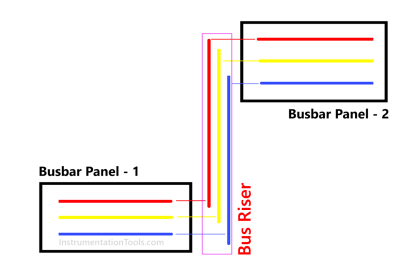
Horizontal and vertical power bus system.
Unit design
Total MCC is distributed into various space units.
Unit types
Contactor and starters, main and feeder units, Arc Shield. Metering compartments such as door-mounted ammeters, voltmeters.
Arrangement for DeviceNet units and Ethernet/IP units, VFD units, PLC units.
Advantages
The MCC offers the following advantages
- Allows control devices to move away from dangerous places.
- It allows centralizing the team in the most appropriate place.
- Facilitates maintenance and the cost of installation is lower.
To design the MCC, the following information must be taken into consideration
Prepare a list of the motors that will be in the MCC indicated for each motor.
- Power in HP or kW.
- Operating voltage.
- Nominal current at full load.
- Starting form.
- If it has reversible movement.
- Control and indicator lamps.
Electrical Motors Maintenance
Finally, the need to periodically carry out preventive-predictive maintenance is an investment. In the event of breakdowns can cause large losses for any organization.
But it is also clear that to carry out this service, it is essential to have to make a few production stops.
Reference: Industrial Power Distribution Systems and Illuminating Systems by Kao Chen 2020.
If you liked this article, then please subscribe to our YouTube Channel for PLC and SCADA video tutorials.
You can also follow us on Facebook and Twitter to receive daily updates.
Read Next:
- What is Electrical Busbar?
- Torque Boosting in VFD
- Types of Motor Enclosures
- What is Electrical Slip Ring?
- Electrical Single Line Diagram


Indeed a great documentation to study