Inst ToolsInst ToolsInst Tools
  • Courses
  • Automation
    • PLC
    • Control System
    • Safety System
    • Communication
    • Fire & Gas System
  • Instrumentation
    • Design
    • Pressure
    • Temperature
    • Flow
    • Level
    • Vibration
    • Analyzer
    • Control Valve
    • Switch
    • Calibration
    • Erection & Commissioning
  • Interview
    • Instrumentation
    • Electrical
    • Electronics
    • Practical
  • Q&A
    • Instrumentation
    • Control System
    • Electrical
    • Electronics
    • Analog Electronics
    • Digital Electronics
    • Power Electronics
    • Microprocessor
  • Request
Search
  • Books
  • Software
  • Projects
  • Process
  • Tools
  • Basics
  • Formula
  • Power Plant
  • Root Cause Analysis
  • Electrical Basics
  • Animation
  • Standards
  • 4-20 mA Course
  • Siemens PLC Course
Reading: #4 PLC Best Practices – Use PLC Flags as Integrity Checks
Share
Font ResizerAa
Inst ToolsInst Tools
Font ResizerAa
  • Courses
  • Design
  • PLC
  • Interview
  • Control System
Search
  • Courses
  • Automation
    • PLC
    • Control System
    • Safety System
    • Communication
    • Fire & Gas System
  • Instrumentation
    • Design
    • Pressure
    • Temperature
    • Flow
    • Level
    • Vibration
    • Analyzer
    • Control Valve
    • Switch
    • Calibration
    • Erection & Commissioning
  • Interview
    • Instrumentation
    • Electrical
    • Electronics
    • Practical
  • Q&A
    • Instrumentation
    • Control System
    • Electrical
    • Electronics
    • Analog Electronics
    • Digital Electronics
    • Power Electronics
    • Microprocessor
  • Request
Follow US
All rights reserved. Reproduction in whole or in part without written permission is prohibited.
Inst Tools > Blog > PLC Tutorials > #4 PLC Best Practices – Use PLC Flags as Integrity Checks

#4 PLC Best Practices – Use PLC Flags as Integrity Checks

One of the best PLC best practices is to use PLC flags as integrity checks. Put counters on PLC error flags to capture any math problems.

Last updated: September 21, 2021 1:23 am
Editorial Staff
PLC Tutorials
No Comments
Share
3 Min Read
SHARE

One of the best PLC best practices is to use PLC flags as integrity checks.

Contents
Use PLC Flags as Integrity ChecksExample

Put counters on PLC error flags to capture any math problems.

Security ObjectiveTarget Group
  The integrity of PLC logicProduct Supplier Integration / Maintenance Service Provider

Use PLC Flags as Integrity Checks

If the PLC code was working fine but suddenly does a divide by zero, investigate. If something is communicating peer to peer from another PLC and the function/logic does a divide by zero when it wasn’t expected, investigate.

Most programmers will ignore the issue as a math error or worse yet, might presume their code is perfect and let the PLC enter a hard fault state.

During code development, engineers need to test and validate their code modules (snippets or routines) by inputting data outside of expected bounds. This may be termed Unit Level Test.

Assign different, locked memory segments for firmware, logic, and protocol stack. Test the protocol stack for abuse cases. Abuse cases could be peculiar flag conditions in a packet header.

Use PLC Flags as Integrity Checks

Example

PLC faults caused by out-of-bounds data are very common. This happens, for example, when an input value causes array indices to go out of bounds, or timers with negative presets, or divide by zero exceptions.

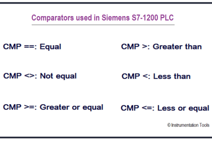
Typical flags of interest are

  • divide by zero
  • counter overflow
  • negative counter or timer preset
  • I/O scan overrun

Why?

Beneficial for…?Why?
      SecurityAttacks on PLCs could include changing their logic, activating a new program, testing new code, loading a new process recipe, inserting auxiliary logic to send messages, or activating some feature.

Since most PLCs do not provide cryptographic integrity checks, flags can be a good indicator if one of the above logic changes happens.
  ReliabilityFlags taken seriously can avoid the PLC running with programming or I/O errors.

Also, if an error occurs, the source of the failure is more obvious.
Maintenance/

References

Standard/frameworkMapping
MITRE ATT&CK for ICSTactic: TA010 – Impair Process Control
Technique:  T0836 – Modify Parameter
  ISA 62443-3-3SR 3.5: Input Validation
SR 3.6: Deterministic Output
  ISA 62443-4-2CR 3.5: Input Validation
CR 3.6: Deterministic Output
  ISA 62443-4-1SI-2: Secure coding standards
SVV-1: Security requirements testing
    MITRE CWECWE-128: Wrap-around
CWE-190: Integer Overflow
CWE-369: Divide by Zero
CWE-754: Improper Check for Unusual or Exceptional Conditions

Source: PLC Security

Don't Miss Our Updates
Be the first to get exclusive content straight to your email.
We promise not to spam you. You can unsubscribe at any time.
Invalid email address
You've successfully subscribed !

Continue Reading

PLC Data Comparison Instructions
What is Masking in PLC?
Free InTouch SCADA Tutorial Course for Beginners
Shutter Door Control using Motor and Limit Switches
What is a GSD File and Why it is required?
What is Fail-safe in Siemens PLC?
Share This Article
Facebook Whatsapp Whatsapp LinkedIn Copy Link
Share
Leave a Comment

Leave a Reply Cancel reply

Your email address will not be published. Required fields are marked *

Stay Connected

128.3kFollowersLike
69.1kFollowersFollow
210kSubscribersSubscribe
38kFollowersFollow

Categories

Explore More

Test and Process Modes in Siemens PLC
What is the OPC Server?
Motor Control Circuits
Why Are Charcoal and Salt Added to an Earthing Pit?
XG5000 Example of Simple Conveyor Control PLC Program
Which Language is Best for PLC Programming?
PLC Ladder Logic for Tanks Filling as per Priority
Push button Motor PLC Logic

Keep Learning

FIFO and LIFO Sequences in PLC

What are FIFO and LIFO Sequences in PLC?

Step-by-step import export in FactoryTalk View

FactoryTalk View Studio – Import and Export Tutorial

Problem on PLC, HMI, VFD, and Motor Circuit

Problem on PLC, HMI, VFD, and Motor Circuit

PLC Training Data Tables FIFO and LIFO

FIFO Instruction in Allen Bradley PLC Programming

HMI

Learn about SCADA and HMI Systems

Siemens PLC Device and Network

Difference Between PLCSIM and PLCSIM Advanced? – Siemens PLC

Indusoft SCADA Modbus Communication

Establishing a Modbus Driver for SCADA Indusoft Web Studio

Electrical Ladder Diagram Control using Timers Example

Electrical Ladder Diagram Control using Timers Example

Learn More

Pressure Gauge Functional Testing

Pressure Gauge Functional Testing

Transformers Questions & Answers Part-4

Transformers Questions & Answers Part-4

Difference between Absolute, Gauge and Differential Pressure Transmitters

Difference between Absolute, Gauge and Differential Pressure Transmitters

Coil Type Timers in Siemens PLC Programming

Coil Type Timers in Siemens PLC Programming

Volume Booster Working Principle

Control Valve Volume Booster Working Principle

Electrical and Instrumentation Engineering Documents

Electrical and Instrumentation – Automation Pre-engineering Documents

Economics of Power Generation Objective Questions

100+ Economics of Power Generation Objective Questions and Answers

Impulse Line Pressure Testing Procedure

Impulse Line Pressure Testing Procedure

Menu

  • About
  • Privacy Policy
  • Copyright

Quick Links

  • Learn PLC
  • Helping Hand
  • Part Time Job

YouTube Subscribe

Follow US
All rights reserved. Reproduction in whole or in part without written permission is prohibited.
Welcome Back!

Sign in to your account

Username or Email Address
Password

Lost your password?