Inst ToolsInst ToolsInst Tools
  • Courses
  • Automation
    • PLC
    • Control System
    • Safety System
    • Communication
    • Fire & Gas System
  • Instrumentation
    • Design
    • Pressure
    • Temperature
    • Flow
    • Level
    • Vibration
    • Analyzer
    • Control Valve
    • Switch
    • Calibration
    • Erection & Commissioning
  • Interview
    • Instrumentation
    • Electrical
    • Electronics
    • Practical
  • Q&A
    • Instrumentation
    • Control System
    • Electrical
    • Electronics
    • Analog Electronics
    • Digital Electronics
    • Power Electronics
    • Microprocessor
  • Request
Search
  • Books
  • Software
  • Projects
  • Process
  • Tools
  • Basics
  • Formula
  • Power Plant
  • Root Cause Analysis
  • Electrical Basics
  • Animation
  • Standards
  • 4-20 mA Course
  • Siemens PLC Course
Reading: PLC Ladder Program for Automatic Car Wash using Siemens TIA Portal
Share
Font ResizerAa
Inst ToolsInst Tools
Font ResizerAa
  • Courses
  • Design
  • PLC
  • Interview
  • Control System
Search
  • Courses
  • Automation
    • PLC
    • Control System
    • Safety System
    • Communication
    • Fire & Gas System
  • Instrumentation
    • Design
    • Pressure
    • Temperature
    • Flow
    • Level
    • Vibration
    • Analyzer
    • Control Valve
    • Switch
    • Calibration
    • Erection & Commissioning
  • Interview
    • Instrumentation
    • Electrical
    • Electronics
    • Practical
  • Q&A
    • Instrumentation
    • Control System
    • Electrical
    • Electronics
    • Analog Electronics
    • Digital Electronics
    • Power Electronics
    • Microprocessor
  • Request
Follow US
All rights reserved. Reproduction in whole or in part without written permission is prohibited.
Inst Tools > Blog > PLC Tutorials > PLC Ladder Program for Automatic Car Wash using Siemens TIA Portal

PLC Ladder Program for Automatic Car Wash using Siemens TIA Portal

A PLC ladder program using Siemens TIA portal to implement an automatic car wash process with programmable logic controllers.

Last updated: October 17, 2023 3:42 pm
Editorial Staff
PLC Tutorials
2 Comments
Share
6 Min Read
SHARE

A PLC ladder program using Siemens TIA portal to implement an automatic car wash process with programmable logic controllers.

Contents
Car Wash using Siemens TIA PortalCar Wash PLC Logic ExplanationNetwork 1: Washing ON and OFFNetwork 2: Conveyor Start DelayNetwork 3: Conveyor MotorNetwork 4: Car Washing and BrushingNetwork 5: Car Rinsing LogicNetwork 6: Car Drying LogicNetwork 7: Car Washing Complete

When a car is driven onto the conveyor, a sensor must detect the car to start the washing process automatically through the stages of washing, brushing, rinsing, and drying.

The conveyor motor runs at a set constant speed throughout the process.

Car Wash using Siemens TIA Portal
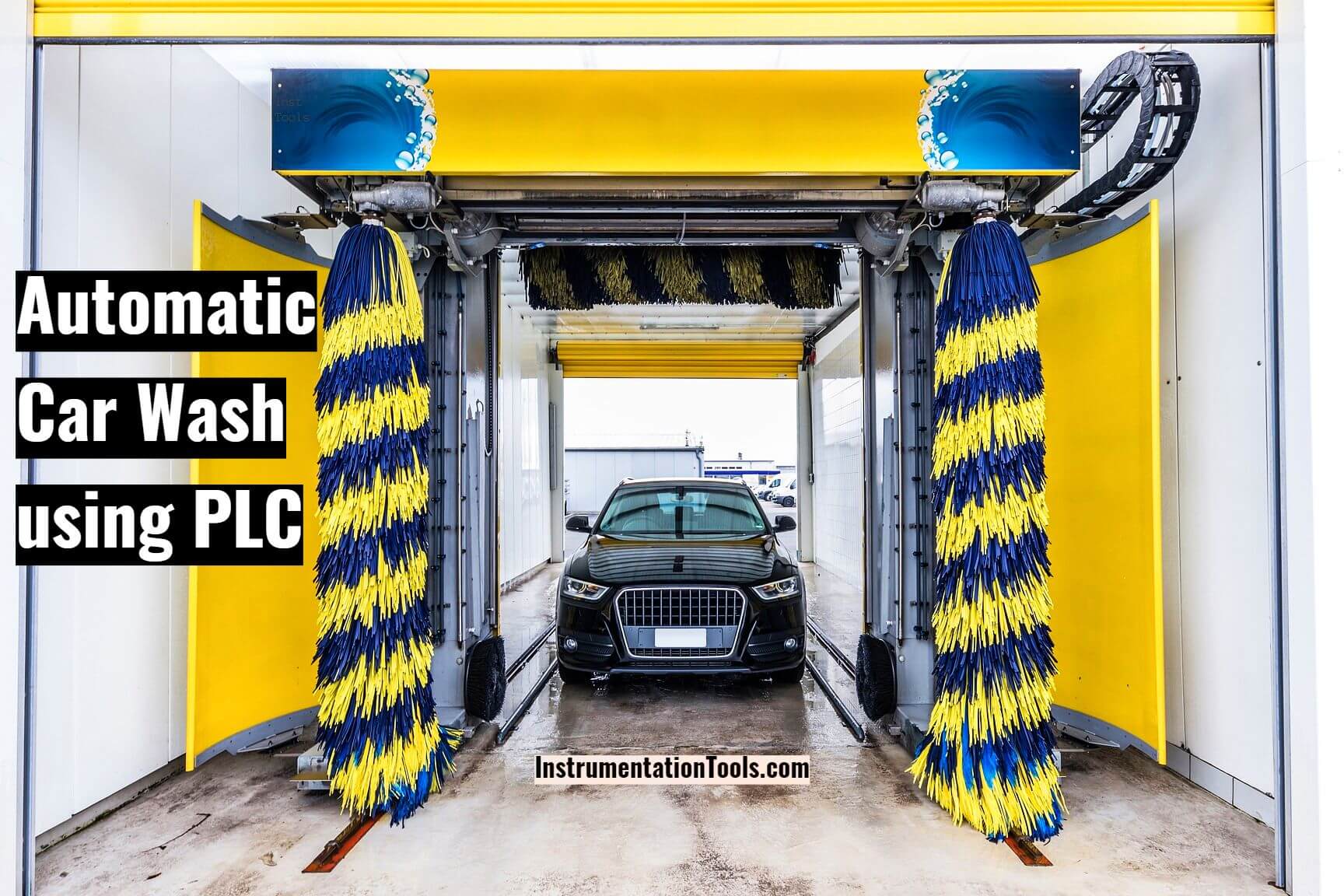
PLC Ladder Program for Automatic Car Wash

The List of Input and Outputs are mentioned in the below table.

AddressDescriptionIO Type
I0.0StartInput
I0.1StopInput
I0.2Car Entry SensorInput
I0.3Car Washing Stage SensorInput
I0.4Car Rinsing Stage SensorInput
I0.5Car Drying stage SensorInput
I0.6Car Exit SensorInput
M0.0 – M0.4Memory BitsMemory
Q0.0Conveyor MotorOutput
Q0.1 – Q0.2Washer/BrushOutput
Q0.3 – Q0.4RinseOutput
Q1.0 – Q1.1DryerOutput
Q1.3Washing in Progress LightOutput
Q1.4Washing Complete LightOutput

Car Wash PLC Logic Explanation

The car wash PLC program is explained step by step with the ladder logic below.

Network 1: Washing ON and OFF
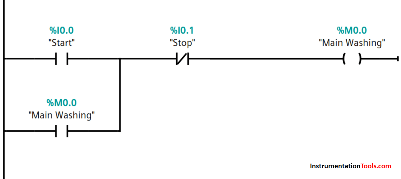
Car Washing ON and OFF PLC Logic

The main control for the start and stop of the car washing process.

Memory bit, M0.0 is set on and off by I0.0 and I0.1 inputs respectively.

Network 2: Conveyor Start Delay
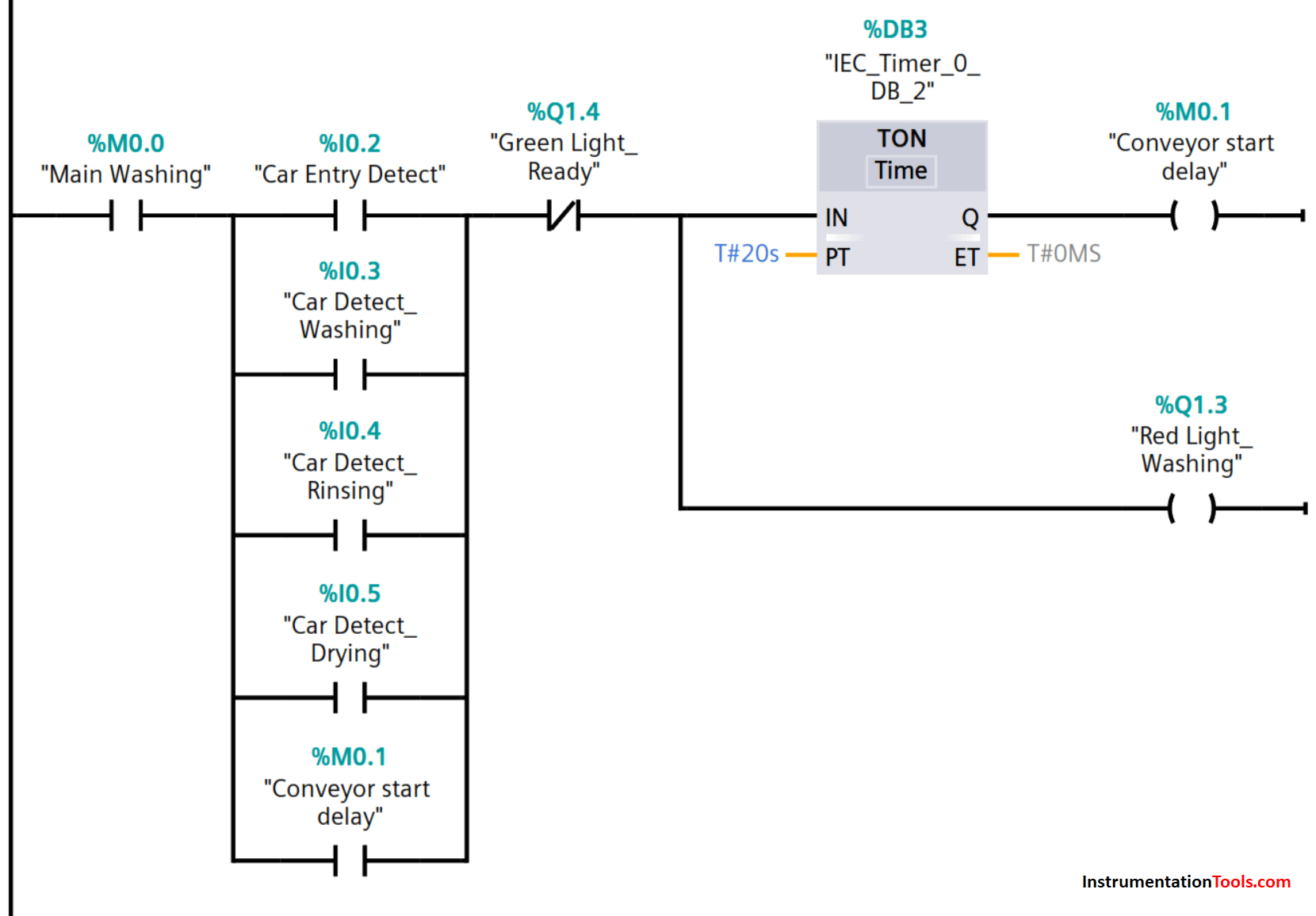
Conveyor Start Delay PLC Program

Once a car is driven onto the conveyor, the sensor detects the presence of a car and sets the on-delay timer for the start of the conveyor motor.

Red light also lit up simultaneously to signal washing in progress. At which time, the driver could exit the car before washing begin.

Network 3: Conveyor Motor

PLC Conveyor Motor Code

After the elapsed time, the conveyor motor is turned on and moves the car to the washing and brushing stage, and the car entry detection sensor deactivates.

The conveyor is interlocked to stop at washing, rinsing, and drying stages.

Network 4: Car Washing and Brushing
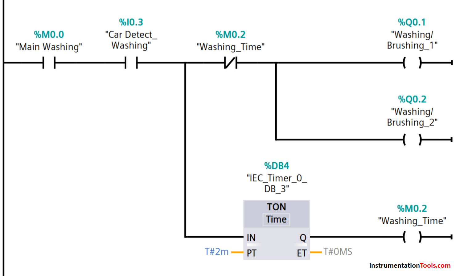
Car Washing and Brushing PLC Program

Washing and brushing begin on detection of the car by sensor assigned to input I0.3.

The timing of the washing and brushing stage also begins and lasts for 2 minutes.

After the set time has elapsed, washing and brushing are stopped by M0.2 and the conveyor then moves the car to the rinsing stage.

The washing/brushing stage car detection sensor is deactivated.

Network 5: Car Rinsing Logic
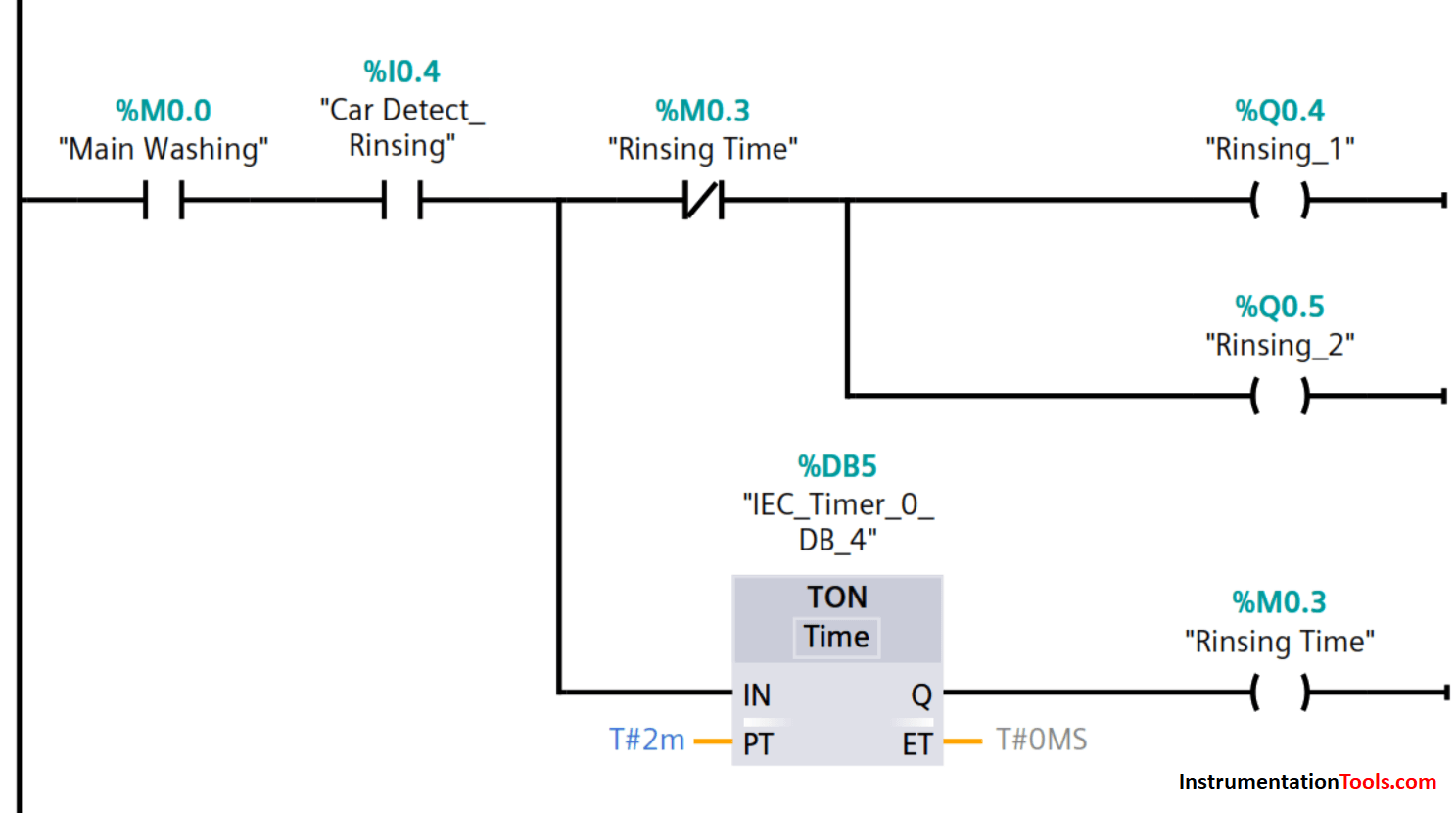
PLC Programming for Car Rinsing

Rinsing begins on detection of the car by sensor assigned to input I0.4.

The timing of the rinsing stage begins and lasts for 2 minutes.

After the set time has elapsed, memory bit M0.3 stops the rinsing and the conveyor moves the car to the drying stage.

The rinsing stage car detection sensor is deactivated.

Network 6: Car Drying Logic
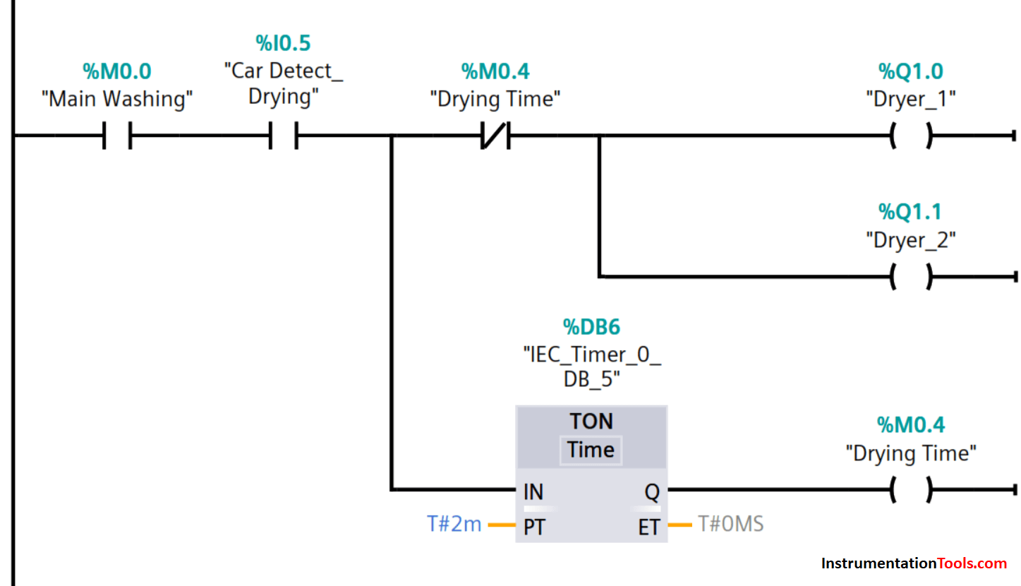
Car Drying Ladder Logic in Tia Portal

Drying begins on detection of the car by sensor assigned to input I0.5.

The timing of the drying stage also begins and lasts for 2 minutes.

After the set time has elapsed, drying is deactivated by M0.4 and the conveyor moves the car to the exit.

The rinsing stage car detection sensor is deactivated.

Network 7: Car Washing Complete
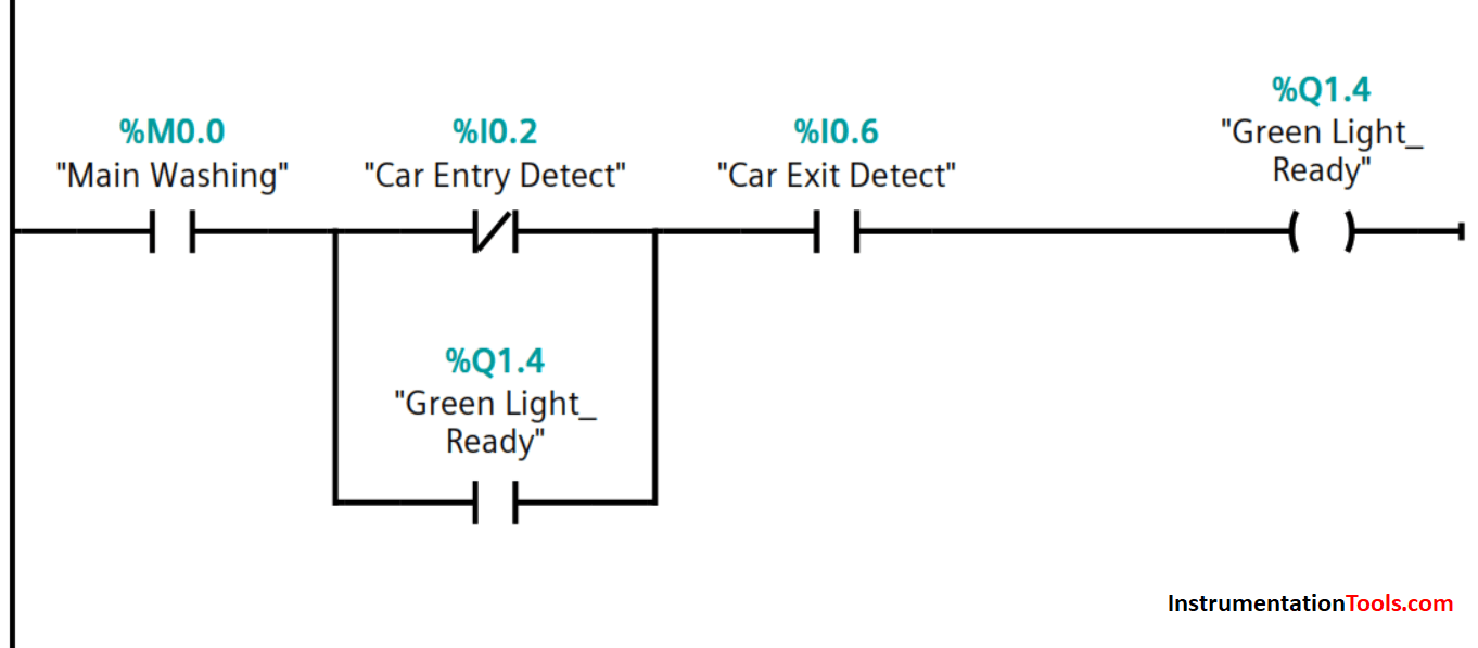
Car Washing Complete PLC Ladder Diagram

At the exit point, the exit detection sensor is activated and a green light lit up signaling the completion of the car washing process. The conveyor motor stops and the red light goes off.

The car can be driven off and the exit sensor deactivates to make the system ready for the next washing process.

Another car can be driven onto the conveyor and once the entry detection sensor activates, the green light goes off and the red light turns on.

The washing process will then start automatically until the stop button is pressed to halt the whole process.

In case, the process is stopped or interrupted by the operation of the stop button, I0.1, or loss of power, the program will continue from the very stage it was interrupted after restarting.

This is a simplified program. A typical program will incorporate additional inputs and outputs control such as directional control valves, pneumatic cylinders for washing/brushing and rinsing the car tyres, roof, rear, and front parts.

Author: Kweku A. Hagan, TMIET

If you liked this article, then please subscribe to our YouTube Channel for PLC and SCADA video tutorials.

You can also follow us on Facebook and Twitter to receive daily updates.

Read Next:

  • Learn PLC in Hindi
  • PLC Interlock Logic
  • PLC Simulator using Excel
  • SCADA and HMI Systems
  • Yokogawa DCS Architecture
Don't Miss Our Updates
Be the first to get exclusive content straight to your email.
We promise not to spam you. You can unsubscribe at any time.
Invalid email address
You've successfully subscribed !

Continue Reading

PLC Program for Boolean Expression
Design a Water Pump PLC Program using CX-Programmer
Instrumentation Earthing
How to Configure an Alarm in InTouch SCADA?
Industrial Automation Pre-Engineering Design Documents – Project & Process
Motor Trip Logic using PLC Programming
Share This Article
Facebook Whatsapp Whatsapp LinkedIn Copy Link
Share
2 Comments
  • Arjun Sundar says:
    July 26, 2021 at 5:32 pm

    Excellent! Thanks for sharing.

    Reply
  • Arvin Mistry says:
    May 12, 2023 at 10:05 pm

    Excellent do more artiçals
    Thank you

    Reply

Leave a Reply Cancel reply

Your email address will not be published. Required fields are marked *

Stay Connected

128.3kFollowersLike
69.1kFollowersFollow
210kSubscribersSubscribe
38kFollowersFollow

Categories

Explore More

How to Design a System Architecture in Industrial Automation?
Rockwell Automation Allen Bradley PLC for Smaller and Medium Projects
Top 100+ SCADA Questions
How to Reduce Relay Noise in PLC Systems?
Pump and Mixer Operations Example: PLC Timer-Based Control
Difference Between Static and Temp Memory in Siemens PLC TIA Portal
PLC Based Industrial Conveyor Ladder Logic
Distributed IO Sharing Between PLC Systems – Technical Insights

Keep Learning

Tags in Functional Block Diagram in Studio 5000

Sheets, Tags, Elements in Functional Block Diagram of Studio 5000

Basics of PID Controllers

PID Controllers in Closed Loop Control Systems – PLC Basics

Save and BR Memory in Siemens PLC Programming

SAVE and BR Memory Instructions in Siemens PLC Programming

Readings Mismatch between Field & Control Room

Readings Mismatch between Field & Control Room ? Why

The STAR-DELTA Auto And Manual Program

STAR-DELTA Auto And Manual Program using XG5000 Software

Types of Allen Bradley PLC

Types of Allen Bradley PLC

Group of Induction Motors

How to Operate a Group of Induction Motors using PLC Logic?

Control Loops

Control Loops Objective Questions and Answers

Learn More

Star to Delta Conversion

Star to Delta and Delta to Star Conversion Formula

Control Valve flow coefficient (Cv)

Why we Measure Control Valve flow coefficient (Cv)?

SCADA Multiple Choice Questions

SCADA Multiple Choice Questions

Embedded Systems

Introduction to Embedded Systems – Features, Types, Applications

Spectrometers Questions and Answers

X-Ray Diffractometers Questions & Answers

Calculate Power in Parallel RC Circuit

Calculate Power in Parallel RC Circuit

Voice Activated Industrial Automation

Voice Activated Industrial Automation Systems

PLC Ladder Logic Example

PLC Ladder Logic Example

Menu

  • About
  • Privacy Policy
  • Copyright

Quick Links

  • Learn PLC
  • Helping Hand
  • Part Time Job

YouTube Subscribe

Follow US
All rights reserved. Reproduction in whole or in part without written permission is prohibited.
Welcome Back!

Sign in to your account

Username or Email Address
Password

Lost your password?