Inst ToolsInst ToolsInst Tools
  • Ask
  • Courses
  • Videos
  • Q & A
    • Interview
      • Instrumentation
      • Electronics
      • Electrical
      • Practical Questions
    • MCQ
      • Instrumentation MCQ
      • Electrical MCQ
      • Electronics MCQ
      • Control Systems MCQ
      • Analog Electronics MCQ
      • Digital Electronics MCQ
      • Power Electronics MCQ
      • Microprocessor MCQ
      • Multiple Choice Questions
  • EE
    • Electronics
      • Electronics Q & A
      • Electronic Basics
      • Electronic Devices & Circuits
      • Electronics Animation
      • Digital Electronics
    • Electrical
      • Electrical Basics
      • Electrical Q & A
      • Power Electronics
      • Electrical Machines
      • Electrical Animation
      • Power Systems
      • Switchgear & Protection
      • Transmission & Distribution
  • Measure
    • Control Valves
    • Calibration
    • Temperature
    • Pressure
    • Flow
    • Level
    • Analyzers
    • Switches
    • Vibration
    • Solenoid Valve
  • Control
    • PLC Tutorials
    • Control Systems
    • Safety Instrumented System (SIS)
    • Communication
    • Fire & Gas System
  • More
    • Design
    • Tools
    • Animation
    • Basics
    • Formulas
    • Standards
    • TextBooks
    • Common
    • Software
    • Excel Tools
    • Erection & Commissioning
    • Process Fundamentals
    • Videos
    • Books
Search
All rights reserved. Reproduction in whole or in part without written permission is prohibited.
Reading: Nutating Disc Flow Meters Working Principle
Share
Notification Show More
Font ResizerAa
Inst ToolsInst Tools
Font ResizerAa
  • Courses
  • PLC Tutorials
  • Control Systems
Search
  • Ask
  • Courses
  • Videos
  • Q & A
    • Interview
    • MCQ
  • EE
    • Electronics
    • Electrical
  • Measure
    • Control Valves
    • Calibration
    • Temperature
    • Pressure
    • Flow
    • Level
    • Analyzers
    • Switches
    • Vibration
    • Solenoid Valve
  • Control
    • PLC Tutorials
    • Control Systems
    • Safety Instrumented System (SIS)
    • Communication
    • Fire & Gas System
  • More
    • Design
    • Tools
    • Animation
    • Basics
    • Formulas
    • Standards
    • TextBooks
    • Common
    • Software
    • Excel Tools
    • Erection & Commissioning
    • Process Fundamentals
    • Videos
    • Books
Follow US
All rights reserved. Reproduction in whole or in part without written permission is prohibited.
Inst Tools > Blog > Animation > Nutating Disc Flow Meters Working Principle

Nutating Disc Flow Meters Working Principle

In Nutating disc flow meters, When fluid enters the chamber, it causes the disc to rotate and this is used to measure flow rate.

Last updated: October 31, 2023 4:10 pm
Editorial Staff
Animation Flow Measurement
1 Comment
Share
3 Min Read
SHARE

Nutating disc flow meters are one of the most common types of positive displacement flow meters. They operate by having a disc mounted to a central ball.

Contents
Nutating Disc Flow MetersHow does the Sensor pick up the Reading?Advantages of Nutating Disc Flow MetersDisadvantages of Nutating Disc Flow Meters

When fluid enters the chamber, it causes the disc to wobble (nutate), transferring the displaced volume to the register.

Nutating Disc Flow Meters

Something to keep in mind is that due to the nutating discs’ nature, the accuracy of this type of flow meter can be adversely affected by fluctuations in liquid viscosity.
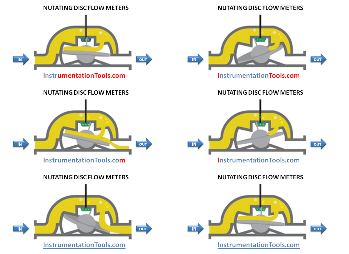
NUTATING DISC FLOW METERS ANIMATION

Liquid enters a precision-machined chamber containing a disc that nutates (wobbles). The position of the disc divides the chamber into compartments containing an exact volume. Liquid pressure drives the disc to wobble and a roller cam causes the nutating disc to make a complete cycle.

This motion is translated into rotary motion by means of a ball and shaft, which is attached to the disc. The movements of the disc are transmitted by a gear train to an indicator/totalizer or pulse transmitter.

There are inherently more leakage paths in this design and it tends to be used where longer flow meter life is required rather than high performance; however, close clearances between the disc and chamber ensure minimum leakage for accurate and repeatable measure of each volume cycle.
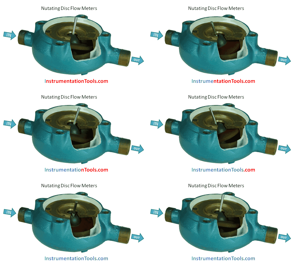
Nutating Disc Flow Meters Working Animation

A disc attached to a sphere is mounted inside a spherical chamber. As fluid flows through the chamber, the disc and sphere unit nutates. The nutation causes a pin, mounted on the sphere perpendicular to the disc, to rock.

Each revolution of the pin indicates a fixed volume of liquid has passed. A mechanical or electromagnetic sensor detects the rocking of the pin and the flow is measured.
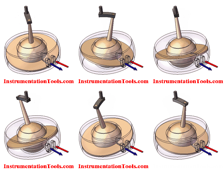
Nutating Flow Meters

How does the Sensor pick up the Reading?

These flow meters may use a Hall sensor to sense the rotation and the same was converted into equivalent flow.

Also Read: How Hall Sensor Works?

Advantages of Nutating Disc Flow Meters

  • May be constructed from a variety of materials.
  • High accuracy and repeatability.

Disadvantages of Nutating Disc Flow Meters

  • Accuracy is adversely affected by viscosities below the meter’s designated threshold.

If you liked this article, then please subscribe to our YouTube Channel for Instrumentation, Electrical, PLC, and SCADA video tutorials.

You can also follow us on Facebook and Twitter to receive daily updates.

Read Next:

  • Vortex Flow Meter Sensors
  • Flow Meter Installation
  • Chart Recorder Flow Measure
  • What is a Hot Wire Anemometer
  • Flow Meter Calibration
Don't Miss Our Updates
Be the first to get exclusive content straight to your email.
We promise not to spam you. You can unsubscribe at any time.
Invalid email address
You've successfully subscribed !
Two Wire Sensor Working Principle and Animation
Basics of Venturi Flow Meter
Basics of Differential Pressure Level Transmitters
How to Read Circular Chart Recorder for Flow Measurement?
Oval Gear Flow Meters – Principle, Advantages, Animation
Share This Article
Facebook Whatsapp Whatsapp LinkedIn Copy Link
Share
1 Comment
  • jmw says:
    February 5, 2020 at 11:49 pm

    The proper designation for the nutating disc meter is as a “Semi-Positive Displacement meter and it is not a true PD meter due to the creation of open flow paths between inlet and outlet during the two transitions which allow a significant amount of unregistered flow.
    The same is true of the rotary or oscillating piston meter though it has become increasingly common to refer to them as such. These two meters are the limit geometric forms of the conic meters. By the beginning of the 20th century when most meters were for utility metering, there were three classes identified, inferential or rotary vane meters (Single jet and multi jet) displacement meters , nutating disc and rotary piston, and Positive displacement meters, reciprocating piston, sliding vane, birotors etc etc..
    Incidentally the last animation uses ports found in the earliest application of the principal, not as a flow meter but as a hydraulic engine patented in 1821 (http://www.dakeynediscengine.com/the-disc-engine.html …… which uses this same animation).The patents by Lewis nash in the 1880s delivered this as a flow meter almost fully finished, requiring only the change to a brass hub to be successful. The protgeometry was considerably different by then.

    Reply

Leave a Reply Cancel reply

Your email address will not be published. Required fields are marked *

Stay Connected

128.3kFollowersLike
69.1kFollowersFollow
208kSubscribersSubscribe
38kFollowersFollow

Categories

Recent Comments

  • Guifty Shimica on Top Non-PLC Certification Courses for Automation Professionals
  • Guifty Shimica on Top Non-PLC Certification Courses for Automation Professionals
  • MIHARITSOA Aina Sitraka on Top Non-PLC Certification Courses for Automation Professionals
  • Vaishnavi on Free Instrumentation Course for Trainee Engineers

Related Articles

Vortex Flow Meter Principle

Vortex Flow meter Animation

Magnetic Float Level Switch Working Animation

Non-Contacting-Radar-Level-Transmitter-Animation

Non Contacting Radar Level Transmitter Animation

Advantages and Disadvantages of Flow Measurement Techniques

Advantages & Disadvantages of Different Flow Meters

Total Organic Carbon Analyzer Working Principle

TOC Analyzer Working Principle

Wedge Flow Meter

Wedge Flow Meter Principle

Flow Transmitter Output Current Calculation

Calculate Flow Transmitter Output Current

vortex flow transmitter

What is a Vortex Flow Meter?

More Articles

Types of Industrial Relays

What is a Relay? Types of Industrial Relays

What is a Bus Coupler in Electrical Panel

What is a Bus Coupler in Electrical Panel?

Nuclear Magnetic Resonance Spectrometer Questions and Answers

Sensivity Enhancement for NMR Spectroscopy Questions & Answers

How Twisted Wire Cables Eliminates Noise Voltage

Inductive Coupling Effects

Redundant Power Supply

How Does Redundant Power Supply Work?

Difference between Soft Starter and VFD

Difference between Soft Starter and VFD

What is a transformer tap changer?

SIS Audit & Assessment - Safety Instrumented System

SIS Audit & Assessment – Safety Instrumented System

Follow US
All rights reserved. Reproduction in whole or in part without written permission is prohibited.
Welcome Back!

Sign in to your account

Username or Email Address
Password

Lost your password?