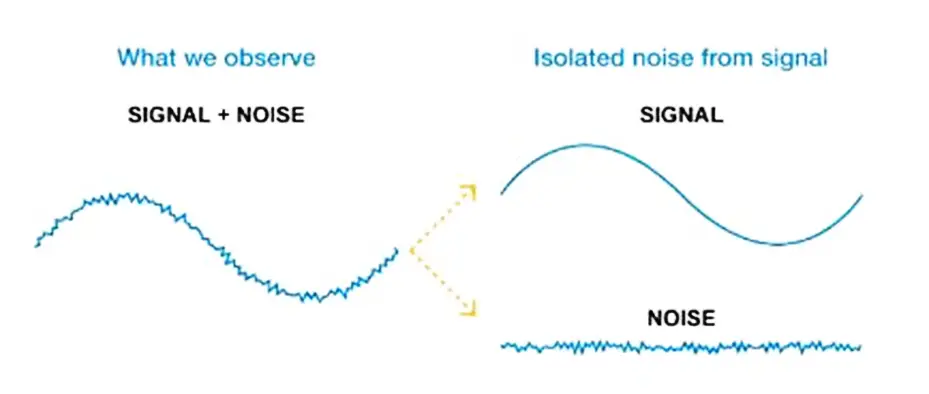
Inst ToolsInst ToolsInst Tools
  • Courses
  • Automation
    • PLC
    • Control System
    • Safety System
    • Communication
    • Fire & Gas System
  • Instrumentation
    • Design
    • Pressure
    • Temperature
    • Flow
    • Level
    • Vibration
    • Analyzer
    • Control Valve
    • Switch
    • Calibration
    • Erection & Commissioning
  • Interview
    • Instrumentation
    • Electrical
    • Electronics
    • Practical
  • Q&A
    • Instrumentation
    • Control System
    • Electrical
    • Electronics
    • Analog Electronics
    • Digital Electronics
    • Power Electronics
    • Microprocessor
  • Request
Search
  • Books
  • Software
  • Projects
  • Process
  • Tools
  • Basics
  • Formula
  • Power Plant
  • Root Cause Analysis
  • Electrical Basics
  • Animation
  • Standards
  • 4-20 mA Course
  • Siemens PLC Course
Reading: The Idea Behind Shielded Cables
Share
Notification Show More
Font ResizerAa
Inst ToolsInst Tools
Font ResizerAa
  • Courses
  • Design
  • PLC
  • Interview
  • Control System
Search
  • Courses
  • Automation
    • PLC
    • Control System
    • Safety System
    • Communication
    • Fire & Gas System
  • Instrumentation
    • Design
    • Pressure
    • Temperature
    • Flow
    • Level
    • Vibration
    • Analyzer
    • Control Valve
    • Switch
    • Calibration
    • Erection & Commissioning
  • Interview
    • Instrumentation
    • Electrical
    • Electronics
    • Practical
  • Q&A
    • Instrumentation
    • Control System
    • Electrical
    • Electronics
    • Analog Electronics
    • Digital Electronics
    • Power Electronics
    • Microprocessor
  • Request
Follow US
All rights reserved. Reproduction in whole or in part without written permission is prohibited.
Inst Tools > Blog > Control Systems > The Idea Behind Shielded Cables

The Idea Behind Shielded Cables

Shielded cables or screened cable is an electrical cable of one or more insulated conductors enclosed by a common conductive layer.

Last updated: September 28, 2022 2:25 pm
Hussien Ghareb
Control Systems
1 Comment
Share
5 Min Read
SHARE

Introduction

One of the most common situations in all plants, “Signal Stuck??” That is after implementing your Automation system, you find out that some of your switches and analog transmitters do not operate as expected, suddenly you find your signals are not in a healthy situation, so what is that and why that is happening? And how can we overcome this situation that we are going to talk about?
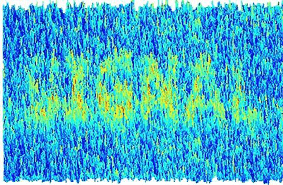
Contents
IntroductionIndustrial NoiseMagnetic FieldMagnetic InductionShielded CablesHow does the shield works?
The Idea Behind Shielded Cables

Industrial Noise

One of the major annoying challenges in the Industrial Automation Field is Noise that could be Mechanically or Electrically, before we can understand how the electricity can make the noise that causes a lot of problems in your system, there are some expressions that you should be concerned with.

Magnetic Field

The magnetic field is a vector field in the neighborhood of a magnet, Electric Current, or changing electric field, in which magnetic forces are observable. The intensity of a magnetic field is proportionally related to the amount of current that causes that Field.

Note, DC Current causes a steady magnetic field unlike the AC Current that causes a rotating or pulsating magnetic field.

Magnetic Induction

Electromagnetic or magnetic induction is the production of an electromotive force across an electrical conductor in a changing magnetic field.

So, what I want to say form the previous two points, that when an AC current travel through a distance it produces an Alternating Field when that field is cutting or rotate across other conductor it produces an electric charges (current) that is proportional to the intensity of that field (AC Current).

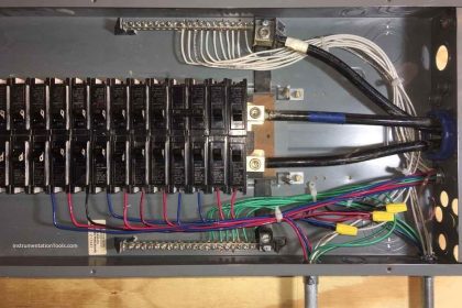
So in our plant we have Power and control circuits, unfortunately you may found one tray that has the two power and control conductors and that is really a good environment for the noise to occur, when the power conductors (Motors – Lightning …) generates that alternating magnetic field that cut the control wires (analog transmitters – 24V switches ..) it produces reasonable amount of charges that have the ability to annoy and bother the control signal from its state, and that is exactly what the noise is.

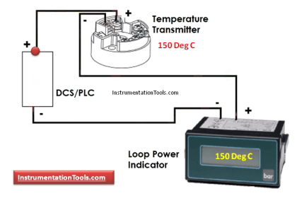
Note as the control signals have very light current (4mA ….) any induced charges by the power Field would certainly make a huge impact on the control signal.
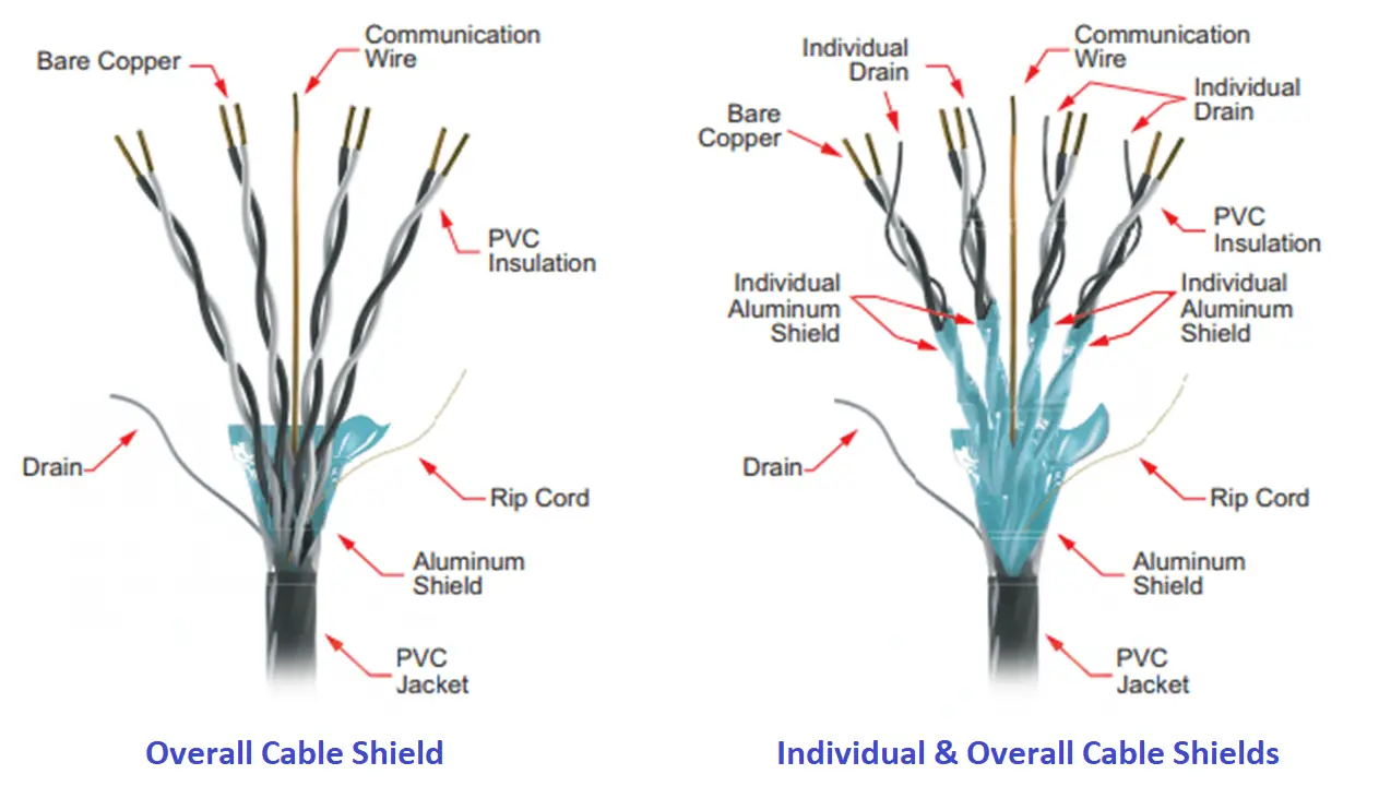
Cable Shields
Image Courtesy: AutomationDirect

Shielded Cables

A shielded cable or screened cable is an electrical cable of one or more insulated conductors enclosed by a common conductive layer.

The shield may be composed of braided strands of copper (or other metal, such as aluminum), a non-braided spiral winding of copper tape, or a layer of conducting polymer.

Signal and Noise

Shielded cables might have a slight cost disadvantage but on the other hand, we really would have a reliable plant that can not be districted by Noise or interfaces with high-power conductors.

How does the shield works?

The enclosure of the insulated wires as we know is made of conductive material, this enclosure will be connected to the earthing of the plant and by its role, the enclosure will absorb any induced charges caused by the interfacing with high voltage conductors, as the enclosure totally surround the wires and it has really no resistance so any induced magnetic charges would be discharged into the earthing of the plant instead of discharging into the control wires that carry our plant signals.

Download the below PDF to read more about the cable shielding.

Title:Basics of Shielding
Author:Phoenix Contact
Format:PDF
Size:2.81 MB
Pages:24
Download:Click Here

If you liked this article, then please subscribe to our YouTube Channel for PLC and SCADA video tutorials.

You can also follow us on Facebook and Twitter to receive daily updates.

Read Next:

  • Tips for Reducing the Noise Signals
  • Where should we Terminate the Cable Shields?
  • Basics of Cable Shields
  • Thermocouple Details
  • PLC Analog I/O Potential Problems
Don't Miss Our Updates
Be the first to get exclusive content straight to your email.
We promise not to spam you. You can unsubscribe at any time.
Invalid email address
You've successfully subscribed !

Continue Reading

Features of PID Controller actions
VFD Simulator Download – Free Yaskawa V1000 Software
Safety in Automation Systems
What is the DDE Protocol?
Installing and Using Modern Industrial Joystick Controls
Learn about PLC, DCS, RTU, SCADA, and PAC
Share This Article
Facebook Whatsapp Whatsapp LinkedIn Copy Link
Share
1 Comment
  • maji says:
    March 3, 2022 at 10:13 am

    great info

    Reply

Leave a Reply Cancel reply

Your email address will not be published. Required fields are marked *

Stay Connected

128.3kFollowersLike
69.1kFollowersFollow
210kSubscribersSubscribe
38kFollowersFollow

Categories

Explore More

ESD System Insights: Signals for Emergency Valve Shutdown Explained
4-20mA Loop Power Supply Questions and Answers
Identify Faults in PID Control Loop
Direct Digital Control (DDC) Systems
How a 4-20mA Transmitter Works?
Difference between Cold Standby and Hot Standby
Readings Mismatch between Field & Control Room ? Why
What is Advanced Process Control (APC)?

Keep Learning

Industrial Automation Solution

How to Choose the Right Industrial Automation Solution?

Cascade-Temperature-Control-System

Cascade Temperature Control System

Feedforward control with feedback trim

Feedforward Control Principle

Alarm Management Practices

Control Room Alarm Management Practices

Workstation Healthiness Checks

Workstation Healthiness Checks

How to Implement Ratio Control in this System

How to Implement Ratio Control in this System?

PID Control Theory

Overview of PID Control terms

EcoStruxure Machine Expert - HVAC - Programming Software

How to Write a Program in Ecostruxure Machine Expert HVAC Software?

Learn More

Globe Valve Disk and Stem Connections

Globe Valve Seat and Disk

Allen Bradley RSLogix 500 PLC Programming

pressure switch ladder-logic diagram

Draw the appropriate Pressure Switch Symbol ?

Cavitation Test Setup

Cavitation Test Setup

Oil in Water Analyzer Principle

Oil in Water Analyzer Working Principle

Circuit Breaker Control Circuit Wiring

Circuit Breaker Control Circuit

Furnace Draft Control System

Furnace Draft Control System

Instrumentation Engineering Materials Test

Instrumentation Materials Test

Menu

  • About
  • Privacy Policy
  • Copyright

Quick Links

  • Learn PLC
  • Helping Hand
  • Part Time Job

YouTube Subscribe

Follow US
All rights reserved. Reproduction in whole or in part without written permission is prohibited.
Welcome Back!

Sign in to your account

Username or Email Address
Password

Lost your password?