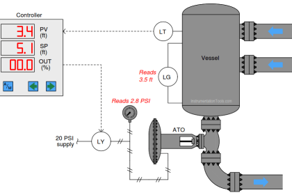
Determine the following voltage drops in this level-sensing circuit when the process level is at a height of 12 feet.
Note that this is not a loop-powered transmitter, but receives its electrical power through separate power conductors (120 volts AC).
Assume negligible (0) voltage drop along the signal conductor lengths:
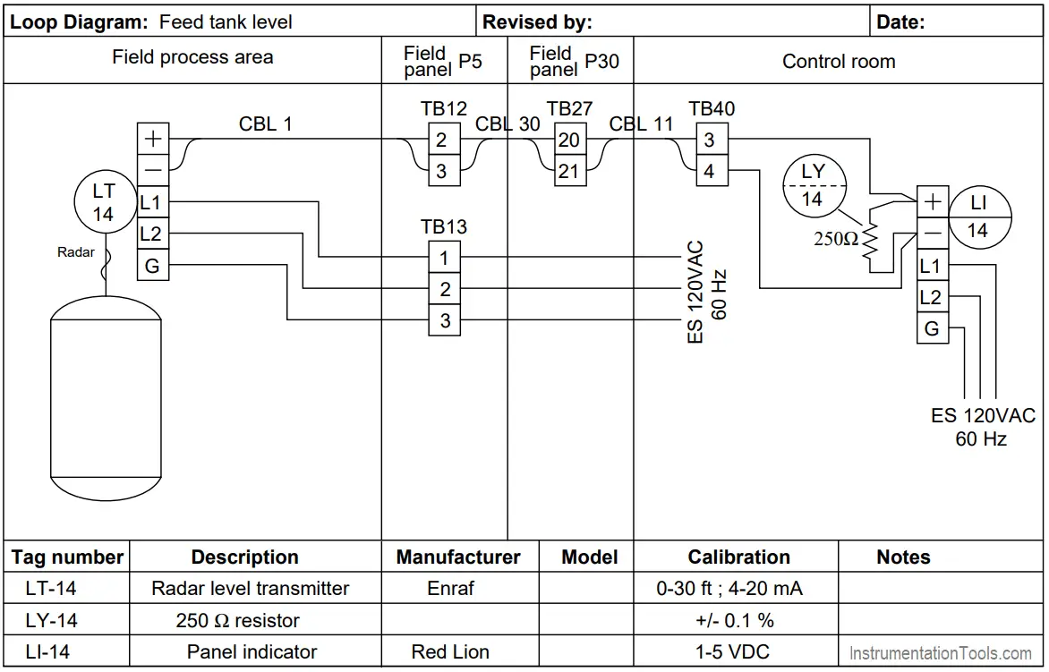
Radar LT Loop Diagram
Question 1
- Voltage drop across transmitter signal terminals =
- Voltage drop between TB40-3 and TB27-21 =
- Voltage drop across 250 Ω resistor =
- Voltage drop between TB12-3 and TB27-21 =
Question 2
Demonstrate how to estimate numerical answers for this problem without using a calculator.
Question 3
If the voltage drop along the signal wiring length were significant rather than zero, how would the voltage calculations be affected?
Would significant loop wire resistance cause a level measurement error? If so, would it result in a high error or a low error?
Question 4
Explain why this particular level transmitter must be self-powered rather than loop-powered as is (more) typical for process transmitters.
Question 5
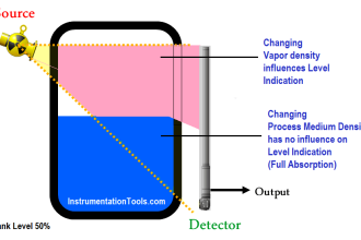
Explain why non-contact radar level transmitters must be used only on metal vessels in order to comply with FCC regulations, while guided-wave radar level transmitters may be used in either metal or nonmetal vessels.
Question 6
As process level increases, will the voltage measured across the transmitter’s terminals increase, decrease, or remain the same?
Question 7
Suppose this self-powered (“4-wire”) level transmitter were replaced be a loop-powered (“2-wire”) level transmitter.
As process level increases, will the voltage measured across the transmitter’s terminals increase, decrease, or remain the same?
Share your answers & explanation with us through the below comments section.
Read Next:
Credits: Tony R. Kuphaldt


Q1. Ans
Voltage drop across transmitter signal terminals = 2.625V
Voltage drop between TB40-3 and TB27-21 = 2.625V
Voltage drop across 250 Ω resistor = 2.625V
Voltage drop between TB12-3 and TB27-21 = 0V
Q6. Ans
As process level increases, Voltage across transmitter terminals decreases. Beacuse Voltage is inversely proporational to Current (V=IR)
Q7. Ans
Voltage is inversely proporational to Current (V=IR), So for ‘Self Powered & Loop Powered’ Voltage decreases as process Level increases.
Q1. Ans
Voltage drop across transmitter signal terminals = ((12ft / 30ft * (20mA-4mA)) + 4mA) * 250ohm = 2.6V
Voltage drop between TB40-3 and TB27-21 = 2.6V
Voltage drop across a 250 Ω resistor = 2.6V
Voltage drop between TB12-3 and TB27-21 = 0V
Q2. I do not understand the question
Q3. Ans
In principle, the transmitter sends an intensity signal of 4-20mA, so the voltage drop should not alter the measurement.
Q4. Ans
Today there are 2-wire radar level transmitters, I understand that one reason for the 4-wire installation to be recommended must be the independent power supply of the radar.
Q5. Ans
The non-contact radar emits electromagnetic waves through the air or fluid, when the material in the deposit is empty it limits the propagation of the wave, so it must be metallic. While the guided wave radar the signal is emitted by the cable or rod and is limited by its length.
Q6. Ans
As the process level increases, the intensity signal (4-20mA) increases; as the voltage in this case is proportional to the current (V = IR) the voltage will increase in the same proportion.
Q7. Ans
In the case of changing to a 2-wire transmitter, the voltage should not be altered by the level variation, since in this case the voltage measured at the transmitter terminals is independent of the 4-20mA output.
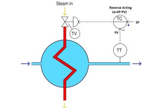
Hello,
Could you please advise if I can connect a pressure transmitter 2 wire directly to PV positioner with out using controller to control the blanketing gas of a tank.
Thanks to clarify with drawing.
Regards
Naji
You must need a controller between the pressure transmitter and control valve. This controller may be a PLC or DCS or external PID controller.
If the pressure transmitter (fieldbus type) have inbuilt PID controller then you may use it directly without external controller. Both transmitter and valve has to support fieldbus communication.