An instrumentation engineer seeking to measure temperature by installing a sensor and thermowell into a flowing fluid stream must make a number of critical evaluations.
Problems
As fluid flows past a thermowell, high-and low-pressure vortices form at both sides. These vortices detach, first from one side and then from the other, in an alternating pattern. This phenomenon is commonly known as vortex shedding.
The differential pressure caused by the alternating vortices produces vortex-induced vibration (VIV), resulting in stresses and causing transverse and axial deflection, which can ultimately lead to fracture of the thermowell.
Is it possible for the engineer to design the thermowell to avoid the VIV-related conditions that could lead to fatigue and failure?
The answer is yes, but only with the right tools.
Thermowell
The success or failure of a given thermowell in a given operational context relates to how closely the VIV frequency matches the natural resonant frequency of the thermowell.
When those two values match each other, the displacement will be its greatest, and damage will be most likely to result.
Both these frequencies can be calculated using a formula created by the American Society of Mechanical Engineers (ASME).
Its present version is ASME PTC 19.3 TW-2016, and it can be used to evaluate the component configuration and operating parameter combinations on four points:
Frequency Limit
the thermowell’s resonance frequency must be high enough that it won’t be reached in operation, avoiding the potential for a match with the VIV frequency.
Dynamic Stress Limit
dynamic stress must not exceed the fatigue stress limit.
Static Stress Limit
steady-state stress must not exceed the stress limit.
Hydrostatic Pressure Limit
external pressure must not exceed the ratings of the tip, shank, or flange.
All four of those limits must be satisfied for the thermowell design to be deemed safe.
Design Calculations
With nearly 20 variables related to process conditions and thermowell dimensions in the ASTM formula, doing the calculations by hand isn’t practical.
Engineers often build the formula in a spreadsheet to facilitate data retention and number crunching.
An engineer must follow the same steps for each situation:
- Design the dimensional parameters
- Place it in the operational contexts (which should include a range of conditions such as normal, startup, maximum, grade change, etc.)
- Create the implementation
- Test it iteration by iteration, gradually working toward a solution able to pass all four evaluation points.
This time-consuming, trial-and-error effort often results in thermowells far thicker and larger than necessary since the formula cannot indicate that a workable result is actually overkill nor does it offer an optimal design solution.
An oversized thermowell slows temperature measurement response time and requires a larger penetration and obstruction into the pipe.
The formula does what it promises: it weighs a given set of parameters and provides a pass or fail grade, but that is all. It does not point the user toward a better solution.
Moving to the next level of functionality demands a more sophisticated approach. There can be tens or even hundreds of temperature measurement points in a processing unit, all needing evaluation.
Thermowell Design Software
The right thermowell design software should include capabilities to help an engineer optimize thermowell design.
As an example, consider a set of hypothetical dimensional and operational parameters for Tag “TE-101.”
What might we want, beyond a simple pass or fail, for the thermowell design software to tell us about Tag TE-101 now, both individually and in context with all of the other temperature tags involved in a unit, process, plant, or enterprise?
Here are some basic functions thermowell design software can provide:
In/Out of scope
The ASME formula includes dimensional standards (wall and tip thickness, etc.) which any thermowell must meet.
If any input variables fall outside acceptable ranges, they are flagged and a more appropriate solution is suggested.
Dimensional issues
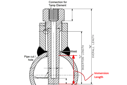
If a thermowell is not compatible with the installation, e.g., longer than the pipe diameter or too short to extend out of a mounting spud, this will be flagged.
A modeling routine can turn the dimensional data into a scale drawing of the thermowell and its mounting to indicate how the assembly fits together and how close the thermowell tip is to the center of the pipe.
Call-Up of similar installations
If a tag calls for a flange mount on a four-inch pipe, the thermowell design software should look for similar installations, including defined dimensions, operational parameters, or other relevant factors, and recommend the same design if possible, to reduce inventory complexity.
Company practices
If a company or facility has preferences for a certain thermowell profile, mounting method, or other consideration, the thermowell design software should suggest these first.
Thermowell catalog
Thermowells used previously should have all their dimensions stored in the thermowell design software database so one can be pulled easily from a listing.
This look-up function can extend to specific part numbers for the facility, or to an approved supplier’s catalog, to minimize the number of potential inventory items.
Simply reporting that a given tag has failed the test at one or multiple conditions is not enough.
The thermowell design software must go to the next step and provide analysis of why it failed, and then go one step farther still and suggest a remedy.
In simple situations this might be an easy change such as shortening the insertion length without sacrificing the desired measurement location, or possibly adding a millimeter or two to the wall thickness.
In a more difficult scenario, it may suggest a totally different solution, such as the VIV-resistant Twisted pair Thermowell profile, or a non-contact temperature measurement solution.
The Twisted Square Thermowell has a unique profile designed to avoid normal wake shedding problems.
Its geometry disrupts the formation of the long vortices, allowing them to form on both sides, so they tend to balance and cancel each other out.
The result is far less vibration, up to a 90% reduction in some cases.
Read Next:
