Inst ToolsInst ToolsInst Tools
  • Courses
  • Videos
  • Q & A
    • Interview
      • Instrumentation
      • Electronics
      • Electrical
      • Practical Questions
    • MCQ
      • Instrumentation MCQ
      • Electrical MCQ
      • Electronics MCQ
      • Control Systems MCQ
      • Analog Electronics MCQ
      • Digital Electronics MCQ
      • Power Electronics MCQ
      • Microprocessor MCQ
      • Multiple Choice Questions
  • EE
    • Electronics
      • Electronics Q & A
      • Electronic Basics
      • Electronic Devices & Circuits
      • Electronics Animation
      • Digital Electronics
    • Electrical
      • Electrical Basics
      • Electrical Q & A
      • Power Electronics
      • Electrical Machines
      • Electrical Animation
      • Power Systems
      • Switchgear & Protection
      • Transmission & Distribution
  • Measure
    • Control Valves
    • Calibration
    • Temperature
    • Pressure
    • Flow
    • Level
    • Analyzers
    • Switches
    • Vibration
    • Solenoid Valve
  • Control
    • PLC Tutorials
    • Control Systems
    • Safety Instrumented System (SIS)
    • Communication
    • Fire & Gas System
  • More
    • Design
    • Tools
    • Animation
    • Basics
    • Formulas
    • Standards
    • TextBooks
    • Common
    • Software
    • Excel Tools
    • Erection & Commissioning
    • Process Fundamentals
    • Videos
    • Books
Search
All rights reserved. Reproduction in whole or in part without written permission is prohibited.
Reading: Pneumatic Signal Piping and Fittings
Share
Notification Show More
Font ResizerAa
Inst ToolsInst Tools
Font ResizerAa
  • Courses
  • PLC Tutorials
  • Control Systems
Search
  • Courses
  • Videos
  • Q & A
    • Interview
    • MCQ
  • EE
    • Electronics
    • Electrical
  • Measure
    • Control Valves
    • Calibration
    • Temperature
    • Pressure
    • Flow
    • Level
    • Analyzers
    • Switches
    • Vibration
    • Solenoid Valve
  • Control
    • PLC Tutorials
    • Control Systems
    • Safety Instrumented System (SIS)
    • Communication
    • Fire & Gas System
  • More
    • Design
    • Tools
    • Animation
    • Basics
    • Formulas
    • Standards
    • TextBooks
    • Common
    • Software
    • Excel Tools
    • Erection & Commissioning
    • Process Fundamentals
    • Videos
    • Books
Follow US
All rights reserved. Reproduction in whole or in part without written permission is prohibited.
Inst Tools > Blog > Instrumentation Design > Pneumatic Signal Piping and Fittings

Pneumatic Signal Piping and Fittings

Learn about pneumatic signal piping and fittings related to industrial instrumentation in oil and gas companies.

Last updated: December 1, 2020 2:51 pm
Editorial Staff
Instrumentation Design
No Comments
Share
5 Min Read
SHARE

Pneumatic piping employed in plants is used to convey air for two basic reasons:

Contents
Pneumatic Piping and FittingsCommon MaterialsLabelling and Colour CodingRouting and ArrangementFittingsBulkhead FittingsTube Fittings

(a) that of supplying Energy for the operation of instruments and other devices, and

(b) that of transmission of Information between instruments.

The integrity of the piping system is essential to avoid loss of the pneumatic supply and degradation of the transmitted signals.

Pneumatic Piping and Fittings

Pneumatic Signal Piping and Fittings

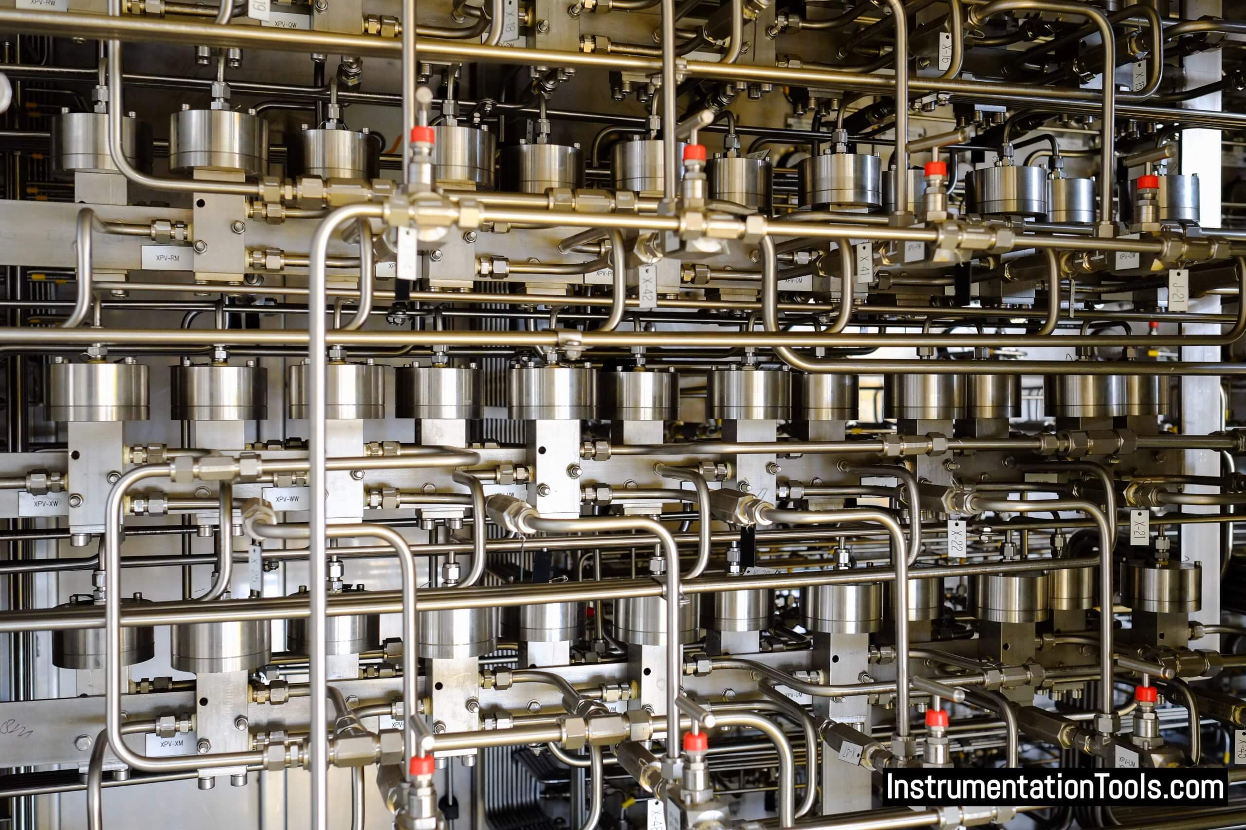
Signal piping is typically 1/4 inch outside diameter (OD) metal or plastic tubing. The signal piping system often includes a test tee and isolating valve at each receiving device to facilitate testing, calibration, or maintenance.

Common Materials

  1. Soft Copper, 1/4 in. OD x 0.030 in. wall thickness
  2. Polyethylene, 1/4 in. OD x 0.040 in. wall thickness
  3. Aluminum, 1/4 in. OD x 0.032 in. wall thickness
  4. Stainless Steel, 1/4 in. OD x 0.030 in. wall thickness

Certain applications may require plated or plastic-coated metal tubing.

Labelling and Colour Coding

Plastic or noncorrosive metal nametags should be attached to bulkhead fittings to identify the signal source, application, and/or other information. Color coded plastic tube can identify use of application, i.e.:

Air supply — RED

Transmitted measurement — ORANGE

Controller output to valve, pneumatic set slave, etc., — YELLOW

Seal (to remote mounted controller) — PURPLE

Set (to remote mounted controller) — BLACK

Branch transmitted measurement to readout element — GREEN

Branch transmitted measurement to readout element — BLUE

All others — NATURAL

Routing and Arrangement

All tubing installation should be in accordance with recognized good practices which generally provide that:

a) Metal tube runs should be routed horizontally and vertically with diagonal routing minimized.

b) All bends in metal tubing should be made with a tool designed for that purpose to prevent kinks or flattening.

c) Tubing runs should be routed to provide maximum access to the control center interior for ease of maintenance and equipment removal.

d) Tubing runs should be grouped for mutual support and neat appearance and secured with noncorrosive metal gang straps. Plastic ties or straps can be used for bundling of plastic tubes or the tubes can be run in wire ways.

e) Sharp bends in plastic tubes should be supported or protected to avoid kinks.

f) Test tees, isolating valves, and quick disconnects should be rigidly supported.

g) Tube fittings should be made up or installed in accordance with the manufacturer’s recommendations.

h) An isolating valve should be provided at each receiver when one signal line serves two or more receiver instruments.

Piping and tubing terminations are normally accomplished through the use of fittings designed to provide leak-free connections. Flared or compression type fittings are normally employed for tube terminations.

Fittings are normally threaded for insertion into tapped pipe thread holes in instruments or other devices.

Plastic tubing terminations are normally the compression type. Special metallic tube fittings, including weld-type and solder-type, are commercially available for special applications.

Fittings

Bulkhead Fittings

Bulkhead fittings provide a means for connection of field piping to the appropriate tube run inside the control center enclosure.

Bulkhead connections can be installed inside the control center enclosure or through the outer surface. The bulkhead fitting normally includes a means for rigid attachment to the control center enclosure and connectors for attachment of tubes at each end.

Tube Fittings

Tees, elbows, couplings, nipples, gauge cocks, shut-off valves, and other tubing components are commonly available in plastic, brass, certain alloys of stainless steel, and other metals. Material selection should normally be based on the application, operating pressures, flowing media, and ambient environmental conditions.

Pipe thread connections should be made leakproof by employing suitable sealing compounds or joint tape.

Interest to add any further points? Share with us through below comments section.

Read Next:

  • Tube Fitting Types
  • Control Valve Actuators
  • Impulse Tube Leak Test
  • Pneumatic Instrumentation
  • What is Pneumatic Cylinder?
Don't Miss Our Updates
Be the first to get exclusive content straight to your email.
We promise not to spam you. You can unsubscribe at any time.
Invalid email address
You've successfully subscribed !

Continue Reading

Design Logic Diagrams with Standard Formats for Process Control
Instrumentation Deliverables Generated from 3D Modeling
Motor Control Circuits
Control Valve Selection Tips
UPS Selection Factors for a Control System
Thermowell Design Guidelines
Share This Article
Facebook Whatsapp Whatsapp LinkedIn Copy Link
Share
Leave a Comment

Leave a Reply Cancel reply

Your email address will not be published. Required fields are marked *

Stay Connected

128.3kFollowersLike
69.1kFollowersFollow
208kSubscribersSubscribe
38kFollowersFollow

Categories

Explore More

Redundant Power Supply for Critical Field Panels
Orifice Flow Meters: Detailed Specifications
% of Reading vs. % of Full Scale Accuracy
Field Instruments Selection Aid
Basics of Fail-safe Circuits
Multiple Thermowell Installations Problems
How to Select a Rotameter? – Parameters and Applications
Process Control Systems Philosophy Concept
Pull Up and Pull Down Switch Circuits
Pressure Gauge Maintenance and Troubleshooting

Keep Learning

Loop Diagram

15 Loop Diagram Questions

Inter Discipline Check (IDC)

What is Inter Discipline Check (IDC)?

Instrumentation Design Engineer

Role of an Instrumentation Design Engineer for Beginners

Interface Level Measurement Selection Guide

Interface Level Measurement Selection Guide

System Architecture in Industrial Automation

How to Design a System Architecture in Industrial Automation?

Process Plant Risk and Safety Management

Safety Roles & Responsibilities of Process Engineering (Detail Design)

How to Solve Cable Tray Sagging

How to Solve Cable Tray Sagging ?

LCS Configuration equipped with LOTO Facility

Motor Control Signal Interface

Discover More

Characteristics of Level Measurement Technologies

Identify Characteristics of Level Measurement Technologies

Pulse Timer Instruction in PLC Programming

Pulse Timer Instruction in PLC Programming

Gas Detection System Abbreviations

Gas Detection System Abbreviations

Compare Serial and Parallel Communication

Difference Between Serial and Parallel Communication

Fieldbus Segment Design

Foundation Fieldbus Segment Design

Best Practices of PLC Wiring

Best Practices of PLC Wiring – Programmable Logic Controller

PLC Karnaugh maps

How to Simplify PLC Coding Using Karnaugh Maps?

Three Phase Induction Motor Interview Questions & Answers

Three Phase Induction Motor Interview Questions & Answers

Follow US
All rights reserved. Reproduction in whole or in part without written permission is prohibited.
Welcome Back!

Sign in to your account

Username or Email Address
Password

Lost your password?