In Olden days, before the usage of 4-20mA transmitters in industries, we were using pneumatic transmitters for our process measurement applications. Briefly, in pneumatic transmitter, the compressed instrument air supply is the source to the pneumatic transmitter and the output of the pneumatic transmitter also in the form of air signal like 3 to 15 psi.
For example, a pneumatic pressure transmitter indicates zero input pressure as 3 PSI output and 100% input pressure signal as 15 PSI instead of 4-20mA as it is not yet invented. Here we are discussing about olden Pneumatic Transmitters.
While electricity is commonly used as a medium for transferring energy across long distances, it is also used in instrumentation to transfer information. A simple 4-20 mA current “loop” uses direct current to represent a process measurement in percentage of span, such as in this example:
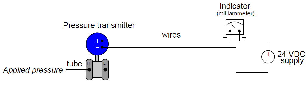
The transmitter senses an applied fluid pressure from the process being measured, regulates electric current in the series circuit according to its calibration (4 mA = no pressure ; 20 mA = full pressure), and the indicator (ammeter) registers this measurement on a scale calibrated to read in pressure units. If the calibrated range of the pressure transmitter is 0 to 250 PSI, then the indicator’s scale will be labeled to read from 0 to 250 PSI as well. No human operator reading that scale need worry about how the measurement gets from the process to the indicator – the 4-20 mA signal medium is transparent to the end-user as it should be.
Air pressure may be used as an alternative signaling medium to electricity. Imagine a pressure transmitter designed to output a variable air pressure according to its calibration rather than a variable electric current. Such a transmitter would have to be supplied with a source of constant pressure compressed air instead of an electric voltage, and the resulting output signal would be conveyed to the indicator via tubing instead of wires:
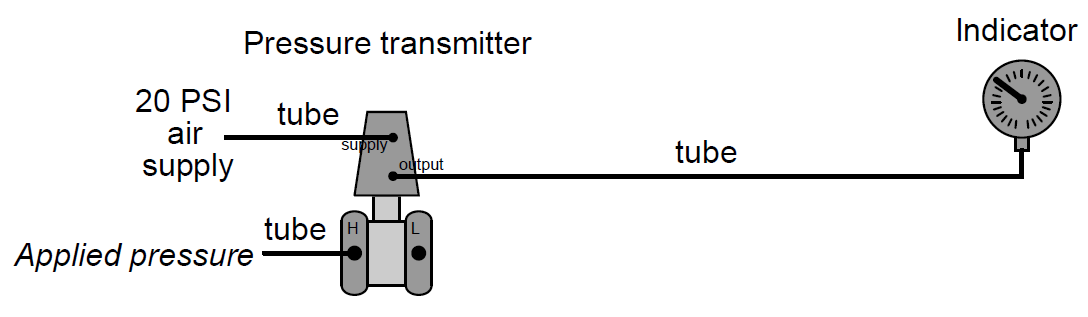
The indicator in this case would be a special pressure gauge, calibrated to read in units of process pressure although actuated by the pressure of clean compressed air from the transmitter instead of directly by process fluid. The most common range of air pressure for industrial pneumatic instruments is 3 to 15 PSI. An output pressure of 3 PSI represents the low end of the process measurement scale and an output pressure of 15 PSI represents the high end of the measurement scale.
Applied to the previous example of a transmitter calibrated to a range of 0 to 250 PSI, a lack of process pressure would result in the transmitter outputting a 3 PSI air signal and full process pressure would result in an air signal of 15 PSI. The face of this special “receiver” gauge would be labeled from 0 to 250 PSI, while the actual mechanism would operate on the 3 to 15 PSI range output by the transmitter. As with the 4-20 mA loop, the end-user need not know how the information gets transmitted from the process to the indicator. The 3-15 PSI signal medium is once again transparent to the operator.
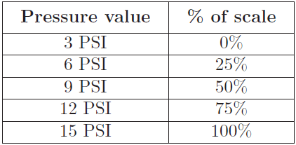
Typically, a 3 PSI pressure value represents 0% of scale, a 15 PSI pressure value represents 100% of scale, and any pressure value in between 3 and 15 PSI represents a commensurate percentage in between 0% and 100%. The following table shows the corresponding current and percentage values for each 25% increment between 0% and 100%. Every instrument technician tasked with maintaining 3-15 PSI pneumatic instruments commits these values to memory, because they are referenced so often:
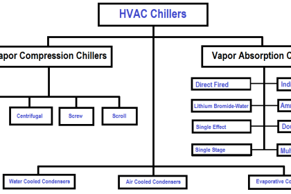
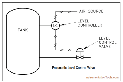
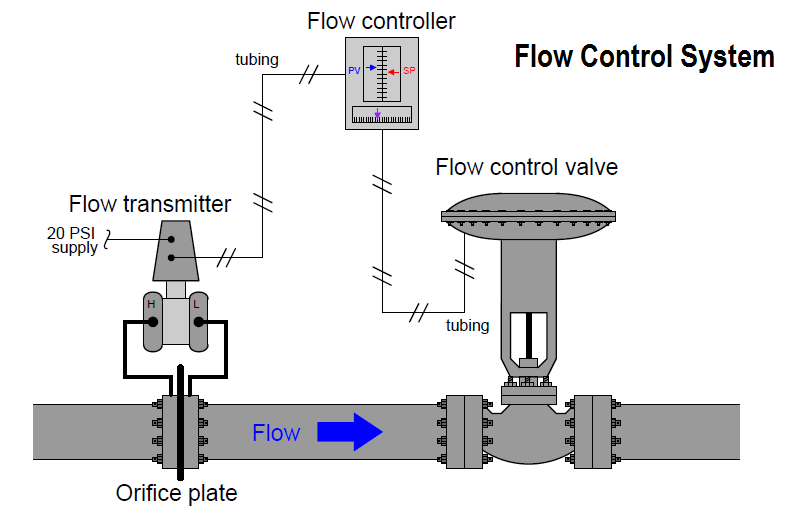
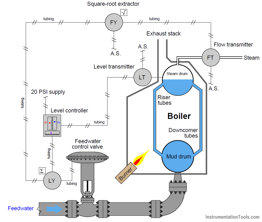
Pneumatic temperature, flow, and level control systems have all been manufactured to use the same principle of 3-15 PSI air pressure signaling. In each case, the transmitter and controller are both supplied clean compressed air at some modest pressure (20 to 25 PSI, usually) and the instrument signals travel via tubing.
The following illustrations show what some of these applications look like:
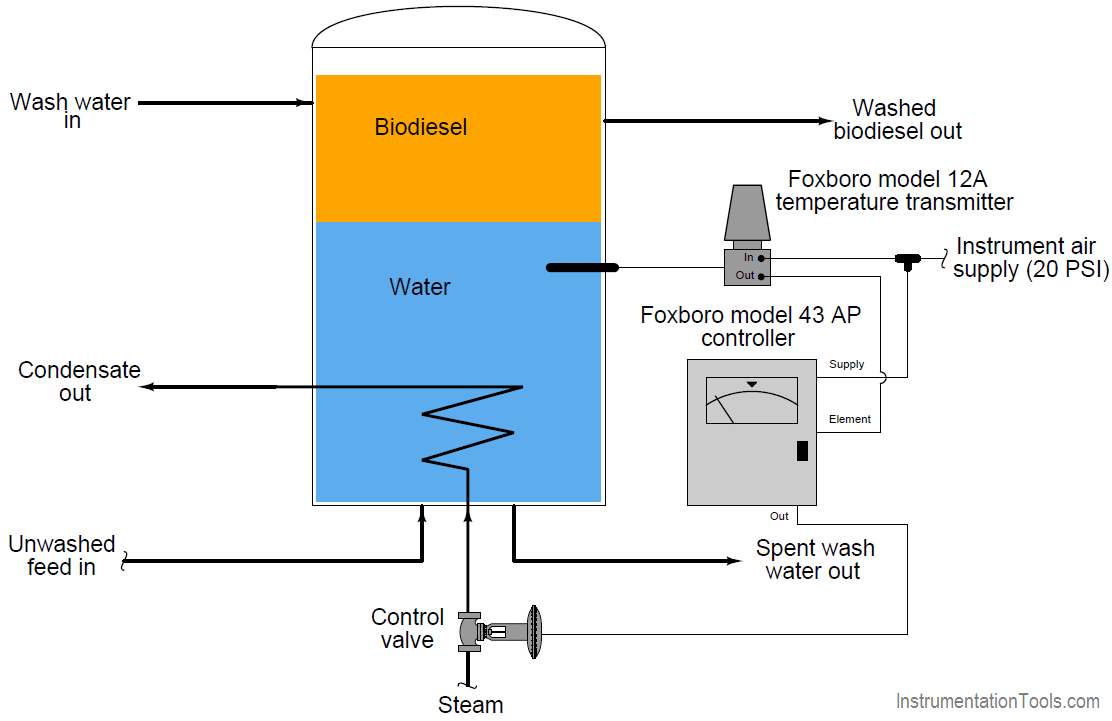
Example : Biodiesel “wash column” temperature control
Example : Flow Control System
Example : Two-element boiler steam drum level control
Instruments operating on compressed air, and process measurement signals transmitted as air pressures through long runs of metal tubing, was the norm for industrial instrumentation prior to the advent of reliable electronic instruments. In honor of this paradigm, instrument technicians were often referred to as instrument mechanics, for these air-powered devices were mechanically complex and in frequent need of adjustment to maintain high accuracy.
Back in the days of control room panels populated by rows and rows of pneumatic indicators, recorders, and controllers, clean and organized routing of all the instrument signal tubes was a significant concern. By contrast, electrical wires are relatively easy to organize through the use of marshaling panels and terminal blocks – bundles of tubes (especially metal tubes!) are not. A photograph taken of the upper rear portion of an old control room panel shows a portion of a marshaling board where dozens of bulkhead-style 1/4 inch instrument tube fittings are organized in neat rows (Note 1), where a multitude of pneumatic instrument signal lines once attached:
Note 1 : the staggered layout of the tube fittings, intended to improve access to each one. Remember that the technician used a 9/16 inch wrench to loosen and tighten the tube fitting nuts, so it was important to have working room between fittings in which to maneuver a wrench.
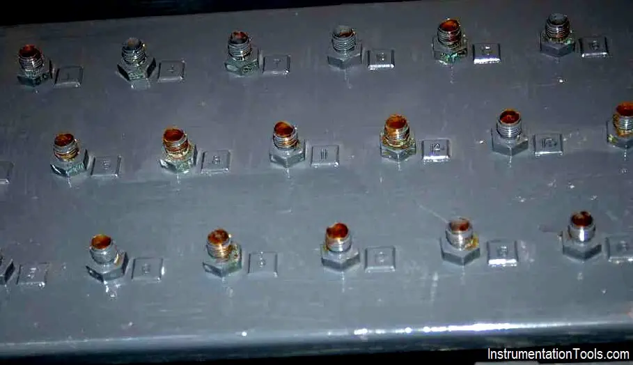
Each bulkhead fitting bears a numbered tag (Note 2), for easy identification and documentation of tube connections. Loop diagrams of pneumatic control systems documented each bulkhead fitting where an instrument signal passed, in the same way that modern loop diagrams document each terminal block where an electrical signal connection is made.
Note 2 : The numbers are difficult to see here, because the entire panel has been painted in a thick coat of grey paint. This particular panel was stripped of all pneumatic instruments and outfitted with electronic instruments, so the rows of bulkhead fittings no longer serve a purpose, but to remind us of legacy technology.
Pneumatic instruments still find wide application in industry, although it is increasingly rare to encounter completely pneumatic control loops. One of the most common applications for pneumatic control system components is control valve actuation, where pneumatic technology still dominates. Not only is compressed air used to create the actuation force in many control valve mechanisms, it is still often the signal medium employed to command the valve’s position.
Quite often this pneumatic signal originates from a device called an I/P transducer, or current-to-pressure converter, taking a 4-20 mA control signal from the output of an electronic controller and translating that information as a pneumatic 3-15 PSI signal to the control valve’s positioner or actuator.