Inst ToolsInst ToolsInst Tools
  • Courses
  • Automation
    • PLC
    • Control System
    • Safety System
    • Communication
    • Fire & Gas System
  • Instrumentation
    • Design
    • Pressure
    • Temperature
    • Flow
    • Level
    • Vibration
    • Analyzer
    • Control Valve
    • Switch
    • Calibration
    • Erection & Commissioning
  • Interview
    • Instrumentation
    • Electrical
    • Electronics
    • Practical
  • Q&A
    • Instrumentation
    • Control System
    • Electrical
    • Electronics
    • Analog Electronics
    • Digital Electronics
    • Power Electronics
    • Microprocessor
Search
  • Books
  • Software
  • Projects
  • Process
  • Tools
  • Basics
  • Formula
  • Power Plant
  • Root Cause Analysis
  • Electrical Basics
  • Animation
  • Standards
  • 4-20 mA Course
  • Siemens PLC Course
Reading: What is Sensor Trim and Output Trim in Smart Transmitter?
Share
Notification Show More
Font ResizerAa
Inst ToolsInst Tools
Font ResizerAa
  • Courses
  • Design
  • PLC
  • Interview
  • Control System
Search
  • Courses
  • Automation
    • PLC
    • Control System
    • Safety System
    • Communication
    • Fire & Gas System
  • Instrumentation
    • Design
    • Pressure
    • Temperature
    • Flow
    • Level
    • Vibration
    • Analyzer
    • Control Valve
    • Switch
    • Calibration
    • Erection & Commissioning
  • Interview
    • Instrumentation
    • Electrical
    • Electronics
    • Practical
  • Q&A
    • Instrumentation
    • Control System
    • Electrical
    • Electronics
    • Analog Electronics
    • Digital Electronics
    • Power Electronics
    • Microprocessor
Follow US
All rights reserved. Reproduction in whole or in part without written permission is prohibited.
Inst Tools > Blog > Calibration > What is Sensor Trim and Output Trim in Smart Transmitter?

What is Sensor Trim and Output Trim in Smart Transmitter?

Last updated: March 12, 2020 11:13 am
Editorial Staff
Calibration Pressure Measurement
1 Comment
Share
3 Min Read
SHARE

Analog electronic process transmitters typically have only two calibration adjustments: one for zero and another for span. Occasionally you may find an analog electronic transmitter with a third adjustment: one for linearity.

Contents
Smart TransmitterSensor Trim and Output Trim

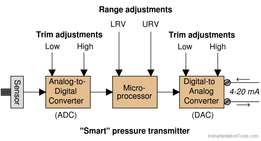
Modern “smart” process transmitters have more components in need of adjustment. A block diagram of a typical smart pressure transmitter shows this very clearly:

Smart Transmitter

Sensor Trim and Output Trim in Smart Transmitter

The purpose of the analog-to-digital converter (ADC) is to translate the pressure sensor’s electrical output signal into a digital number the microprocessor can understand.

Likewise, the purpose of the digital-to-analog converter (DAC) is to translate the digital output of the microprocessor into a 4 to 20 mA DC current signal representing measured pressure. The procedure of calibrating the ADC is called a sensor trim, while the process of calibrating the DAC is called an output trim.

Explain the importance of performing both a sensor trim and an output trim whenever calibrating a “smart” transmitter. In other words, explain why it is not enough to simply program LRV and URV values into the microprocessor (e.g. LRV = 0 PSI ; URV = 30 PSI) and declare the job finished.

Furthermore, explain what external calibration equipment must be connected to the transmitter to complete a sensor trim procedure, and also what external calibration equipment must be connected in order to complete an output trim procedure.

Sensor Trim and Output Trim

Simply setting the LRV and URV values is not actually calibrating the transmitter to accurately correspond to reality.

If this concept is hard to grasp, imagine a transmitter whose LRV and URV values are set perfectly, and whose DAC is calibrated just right, but whose ADC suffers from a zero shift. The microprocessor will “think” the pressure is something different from what it really is, and it will output an incorrect (zero-shifted) milliamp signal as a result.

In order to perform a sensor trim, you must connect a known pressure source (a standard) to the transmitter’s input port and correlate that standard pressure to the pressure value registered by the microprocessor.

When trimming the output, you must connect a precise milli-ammeter in series with the transmitter’s output current to correlate the intended current signal of the microprocessor to the actual current.

Credits: Tony R. Kuphaldt

Read Next:

  • HART Communicator Analysis
  • Square-Root in Flow Transmitter
  • What are Instrument Errors?
  • DP Level Transmitter Corrections
  • Linear to Square-root conversion
Don't Miss Our Updates
Be the first to get exclusive content straight to your email.
We promise not to spam you. You can unsubscribe at any time.
Invalid email address
You've successfully subscribed !

Continue Reading

Flow Meter Calibration
Bourdon Tube Pressure Gauge
Pressure Gauge Maintenance and Troubleshooting
When to use a Diaphragm Seal?
Step by Step Guide for Gas Flow Meter Calibration
What is Capillary Tubing? – Advantages and Disadvantages
Share This Article
Facebook Whatsapp Whatsapp LinkedIn Copy Link
Share
1 Comment
  • MohdKusno says:
    September 9, 2020 at 4:09 am

    Learn instrument

    Reply

Leave a Reply Cancel reply

Your email address will not be published. Required fields are marked *

Stay Connected

128.3kFollowersLike
69.1kFollowersFollow
208kSubscribersSubscribe
38kFollowersFollow

Categories

Explore More

What is Reliability Centered Maintenance? (RCM)
Pressure Measurement Objective Questions
History of Measurement
Instrument Zero and Span Calibration
Pressure Transmitter Troubleshooting Tips
Calibration MCQ – Terminology and Glossary Questions
What is Field Transmitter Damping ?
Well Manometer Principle

Keep Learning

Capacitance Pressure Sensor Principle

Electronic Pressure Sensors Principle

Pressure gauge mechanism

How Measurement Span of Pressure Gauge Could be Changed?

Instrument Calibration Record

How to Create Calibration Records?

RTD Calibration

RTD Calibration

Fieldbus Flow Transmitter Configuration

Fieldbus Flow Transmitter Configuration

Pressure transmitter Calibration Setup

Instruments Calibration Procedures

Calibration of a Strain Gage Load Cell

Shunt Calibration of a Strain Gauge Load Cell

Pressure Gauge Accessories

Pressure Gauge Accessories Questions and Answers

Learn More

Four Wire RTD Principle

How a 4 Wire RTD Works ?

Digital Electronics Multiple Choice Questions

Integrated Injection Logic (IIL) Objective Questions

Open Loop Control Block Diagram

Self-regulating Processes – Liquid Flow Control

Digital Electronics Multiple Choice Questions

Memory Devices Objective Questions – Part 3

safety gas analyzer

Safety Gas Analyzers

Turbine Flow Meter Animation

Turbine Flow Meter – Principle, Advantages, Disadvantages

Ultrasonic-Level-Transmitter-Animation

Ultrasonic Level Transmitter Animation

Power Systems Questions & Answers

Power Systems MCQ Series 6

Follow US
All rights reserved. Reproduction in whole or in part without written permission is prohibited.
Welcome Back!

Sign in to your account

Username or Email Address
Password

Lost your password?