Inst ToolsInst ToolsInst Tools
  • Ask
  • Courses
  • Videos
  • Q & A
    • Interview
      • Instrumentation
      • Electronics
      • Electrical
      • Practical Questions
    • MCQ
      • Instrumentation MCQ
      • Electrical MCQ
      • Electronics MCQ
      • Control Systems MCQ
      • Analog Electronics MCQ
      • Digital Electronics MCQ
      • Power Electronics MCQ
      • Microprocessor MCQ
      • Multiple Choice Questions
  • EE
    • Electronics
      • Electronics Q & A
      • Electronic Basics
      • Electronic Devices & Circuits
      • Electronics Animation
      • Digital Electronics
    • Electrical
      • Electrical Basics
      • Electrical Q & A
      • Power Electronics
      • Electrical Machines
      • Electrical Animation
      • Power Systems
      • Switchgear & Protection
      • Transmission & Distribution
  • Measure
    • Control Valves
    • Calibration
    • Temperature
    • Pressure
    • Flow
    • Level
    • Analyzers
    • Switches
    • Vibration
    • Solenoid Valve
  • Control
    • PLC Tutorials
    • Control Systems
    • Safety Instrumented System (SIS)
    • Communication
    • Fire & Gas System
  • More
    • Design
    • Tools
    • Animation
    • Basics
    • Formulas
    • Standards
    • TextBooks
    • Common
    • Software
    • Excel Tools
    • Erection & Commissioning
    • Process Fundamentals
    • Videos
    • Books
Search
All rights reserved. Reproduction in whole or in part without written permission is prohibited.
Reading: How to Use the Shift and Rotate Instructions in PLC?
Share
Notification Show More
Font ResizerAa
Inst ToolsInst Tools
Font ResizerAa
  • Courses
  • PLC Tutorials
  • Control Systems
Search
  • Ask
  • Courses
  • Videos
  • Q & A
    • Interview
    • MCQ
  • EE
    • Electronics
    • Electrical
  • Measure
    • Control Valves
    • Calibration
    • Temperature
    • Pressure
    • Flow
    • Level
    • Analyzers
    • Switches
    • Vibration
    • Solenoid Valve
  • Control
    • PLC Tutorials
    • Control Systems
    • Safety Instrumented System (SIS)
    • Communication
    • Fire & Gas System
  • More
    • Design
    • Tools
    • Animation
    • Basics
    • Formulas
    • Standards
    • TextBooks
    • Common
    • Software
    • Excel Tools
    • Erection & Commissioning
    • Process Fundamentals
    • Videos
    • Books
Follow US
All rights reserved. Reproduction in whole or in part without written permission is prohibited.
Inst Tools > Blog > PLC Tutorials > How to Use the Shift and Rotate Instructions in PLC?

How to Use the Shift and Rotate Instructions in PLC?

Last updated: March 4, 2021 1:12 pm
Editorial Staff
PLC Tutorials
1 Comment
Share
6 Min Read
SHARE

Let’s study the working shift and rotate instructions and its function in Siemens PLC programming with example ladder logic.

Contents
Shift and Rotate Instructions in PLCBlock DescriptionShift Right Integer:Shift Right Double Integer:Shift right Word:Shift Right double Word:Rotate Right Double Word:Ladder LogicNetwork 1:Network 2:Network 3:Network 4: Network 5 :Variable Table:

Shift and Rotate Instructions in PLC

Shift and Rotate Instructions in PLC

Block Description

Shift Right Integer:

Shift Right Integer instruction is used to shift bits 0 to 15 of input IN bit by bit to the right. The input N specifies the number of bits by which to shift.

After shifting, the bit position shifted in from the left to fill vacated bit position are filled with 0 if 15th bit (Sign bit) of input data is 0 or 1 id 15th bit (Sign bit) of input is 1.

Example 1:

Input IN: 1010 0110 1000 1000

N: 2

OUT: 1110 1001 1010 0010

Example 2:

Input IN :0011 0001 0001 1100

N:2

Output OUT : -0000 1100 0100 0111

Shift Right Double Integer:

Shift Right Double Integer instruction is used to shift bits 0 to 31 of input IN bit by bit to the right. The input N specifies the number of bits by which to shift.

After shifting, the bit position shifted in from the left to fill vacated bit position are filled with 0 if 15th bit (Sign bit) of input data is 0 or 1 id 15th bit (Sign bit) of input is 1.

Example 1:

Input IN: 0001 0111 1010 0111 1110 0011 1010 0101

N: 3

OUT: 0000 0010 1111 0100 1111 1100 0111 0100

Example 2:

Input IN :1011 1111 1111 0100 1110 0011 1010 0101

N:3

Output OUT : -1111 0111 1111 1110 1001 1100 0111 0100

Shift right Word:

Shift right Word instruction is used to shift bits 0 to 15 of input IN bit by bit to the right. The input N specifies the number of bits by which to shift.

After shifting, the bit position shifted in from the left to fill vacated bit position are filled with 0.

Example 1:

Input IN: 0011 0110 1100 0110

N: 2

OUT: 0000 1101 1011 0001

Example 2:

Input IN: 1111 0110 1100 1111

N: 2

Output OUT: -0011 1101 1011 0011

Shift Right double Word:

Shift Right double Word instruction is used to shift bits 0 to 31 of input IN bit by bit to the right. The input N specifies the number of bits by which to shift. After shifting, the bit positions shifted in from the left to fill vacated bit position are filled with 0.

Example 1:

Input IN: 0011 0110 1110 0011 1000 0110 0111 0111

N: 3

OUT: 0000 0110 1101 1100 0111 0000 1100 1110

Example 2:

Input IN : 1111 0110 1110 0011 1000 0110 0111 0111

N:3

Output OUT: -0001 1110 1101 1100 0111 0000 1100 1110

Read: Data Inside PLC

Rotate Right Double Word:

Rotate Right Double Word instruction is used to rotate the entire content of input IN bit by bit to the right. Input N specifies the number of bits by which to rotate.

The bit position shifted in from the left is assigned the logic states of the bits which were rotated out to the right.

Example 1:

Input IN : 1100 0110 0111 0011 0101 0101 1010 1100

N: 2

Output OUT: 0011 0001 1001 1100 1101 0101 0110 1011

Ladder Logic

Shift Register in PLC
Rotate Instructions in PLC

Network 1:

Input I0.0 is pressed, SHR_I instruction reads the value in MW0, shifting 2 bit right and result the output to MW4. Q0.0 enables as long as I0.0 enables.

Network 2:

Input I0.0 is pressed, SHR_DI  instruction read the value in MD8, Shifting 3 bit right and result the output to MW14. Q0.1 enables as long as I0.0 enables.

Network 3:

Input I0.0 is pressed, SHR_W instruction reads the value in MW18, shifting 2 bit towards rights and result the output to MW22. Q0.2 enables as long as I0.0 enables.
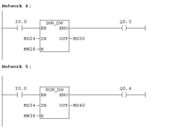
Network 4:

Input I0.0 is pressed, SHR_DW instruction reads the value in, Shifting 3 bit towards the right and result the output to MD30. Q0.3 enables as long as I0.0 enables.

 Network 5 :

Input I0.0 is pressed, ROR_DW instruction reads the value in MD34, rotate the bits towards and result the output to MD40. Q0.4 enables as long as I0.0 enables.

Variable Table:

Variable is used to view the inputs and outputs in different formats.

Shift Register Variables in PLC

In Siemens, MW is the address used for integer data, MD is the address used for double integer data.

Status Value in Variable table is used to see the input and output values.

Modify the value in the variable table is used to give input data.

Author: Hema Sundaresan

If you liked this article, then please subscribe to our YouTube Channel for PLC and SCADA video tutorials.

You can also follow us on Facebook and Twitter to receive daily updates.

Read Next:

  • Bitwise Logical Operations
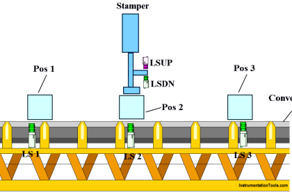
  • PLC Packaging System
  • Memory Instructions in PLC
  • Siemens PLC programming
  • Pulse Timer Instruction in PLC
Don't Miss Our Updates
Be the first to get exclusive content straight to your email.
We promise not to spam you. You can unsubscribe at any time.
Invalid email address
You've successfully subscribed !
#5 PLC Best Practices – Cryptographic and Checksum Integrity Checks
Introduction to SCADA
What is Function Module in Siemens PLC?
Difference between DCS, PLC, and RTU ?
Yokogawa DCS and SIS System Architecture
Share This Article
Facebook Whatsapp Whatsapp LinkedIn Copy Link
Share
1 Comment
  • P Maruthi Prasad says:
    February 1, 2020 at 7:08 am

    Dear team,
    Thank you so much for valuable information , in the simplest way possible.
    great job.

    Reply

Leave a Reply Cancel reply

Your email address will not be published. Required fields are marked *

Stay Connected

128.3kFollowersLike
69.1kFollowersFollow
208kSubscribersSubscribe
38kFollowersFollow

Categories

Recent Comments

  • Guifty Shimica on Top Non-PLC Certification Courses for Automation Professionals
  • Guifty Shimica on Top Non-PLC Certification Courses for Automation Professionals
  • MIHARITSOA Aina Sitraka on Top Non-PLC Certification Courses for Automation Professionals
  • Vaishnavi on Free Instrumentation Course for Trainee Engineers

Related Articles

How to Select the Right Encoder for Your Machine

How to Select the Right Encoder for Your Machine?

Difference Between PNP and NPN Sensors

Difference Between PNP and NPN Sensors

How to Download Rslogix Free

Download Allen Bradley RSLogix PLC Software

Downloading Free PLC software

Step by Step Guidelines for Downloading Free PLC software

PLC Water Project

Smart Spray System using Wecon PLC

PID with Practical Example

PID with Practical Example

Latching and Unlatching in PLC Programming for Beginners

Latching and Unlatching in PLC Programming Example

Difference Between PLC and SCADA

Difference Between PLC and SCADA

More Articles

Microprocessors Objective Questions

Microprocessors Objective Questions – Set 4

Control Systems Multiple Choice Questions

Function and Application of FIFO Block

How to use FIFO Block in TIA Portal? – Siemens PLC Programming

Feedforward Control

Feedforward Vs Feedback Control

Smart DP transmitter Formula

Smart DP Transmitter Flow Meter Calculations

Electrical Machines Questions and Answers

Autotransformers

Turbine Flow Meters Working Animation

Turbine Flow Meters Animation

Siemens PLC

Five Types of PLC Programming languages

Follow US
All rights reserved. Reproduction in whole or in part without written permission is prohibited.
Welcome Back!

Sign in to your account

Username or Email Address
Password

Lost your password?