Inst ToolsInst ToolsInst Tools
  • Courses
  • Automation
    • PLC
    • Control System
    • Safety System
    • Communication
    • Fire & Gas System
  • Instrumentation
    • Design
    • Pressure
    • Temperature
    • Flow
    • Level
    • Vibration
    • Analyzer
    • Control Valve
    • Switch
    • Calibration
    • Erection & Commissioning
  • Interview
    • Instrumentation
    • Electrical
    • Electronics
    • Practical
  • Q&A
    • Instrumentation
    • Control System
    • Electrical
    • Electronics
    • Analog Electronics
    • Digital Electronics
    • Power Electronics
    • Microprocessor
  • Request
Search
  • Books
  • Software
  • Projects
  • Process
  • Tools
  • Basics
  • Formula
  • Power Plant
  • Root Cause Analysis
  • Electrical Basics
  • Animation
  • Standards
  • 4-20 mA Course
  • Siemens PLC Course
Reading: Identify Instruments in Piping and instrumentation Diagram
Share
Notification Show More
Font ResizerAa
Inst ToolsInst Tools
Font ResizerAa
  • Courses
  • Design
  • PLC
  • Interview
  • Control System
Search
  • Courses
  • Automation
    • PLC
    • Control System
    • Safety System
    • Communication
    • Fire & Gas System
  • Instrumentation
    • Design
    • Pressure
    • Temperature
    • Flow
    • Level
    • Vibration
    • Analyzer
    • Control Valve
    • Switch
    • Calibration
    • Erection & Commissioning
  • Interview
    • Instrumentation
    • Electrical
    • Electronics
    • Practical
  • Q&A
    • Instrumentation
    • Control System
    • Electrical
    • Electronics
    • Analog Electronics
    • Digital Electronics
    • Power Electronics
    • Microprocessor
  • Request
Follow US
All rights reserved. Reproduction in whole or in part without written permission is prohibited.
Inst Tools > Blog > Control Systems > Identify Instruments in Piping and instrumentation Diagram

Identify Instruments in Piping and instrumentation Diagram

Last updated: January 10, 2020 9:26 am
Editorial Staff
Control Systems
1 Comment
Share
0 Min Read
SHARE

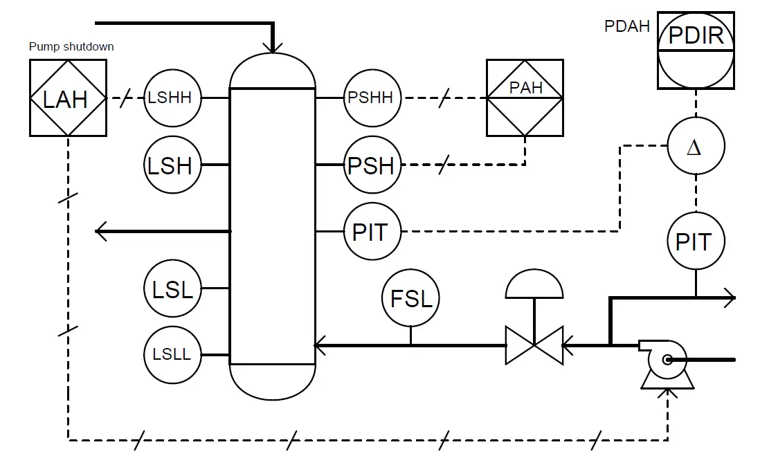
Identify the meanings of the following instruments in this Piping and instrumentation Diagram (P&ID).

Contents
Piping and instrumentation DiagramSolution:

Piping and instrumentation Diagram

Identify Instruments in Piping and instrumentation Diagram

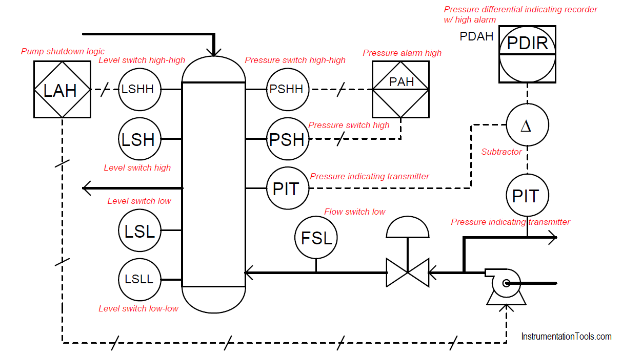
Solution:

The below Piping and instrumentation (P&ID) Diagram shows the abbreviations or meaning of the instrument symbols.

Piping and instrumentation Diagram Abbreviations

Credits: Tony R. Kuphaldt
Read Next:

  • Architecture of Instrumentation
  • Control loop in P&ID
  • Instrumentation Symbols Legend
  • Schematic Diagram
  • Industrial Instrumentation Quiz
  • 100 PLC Quiz Questions
Don't Miss Our Updates
Be the first to get exclusive content straight to your email.
We promise not to spam you. You can unsubscribe at any time.
Invalid email address
You've successfully subscribed !

Continue Reading

Instrumentation and Electrical Teams Interactions (Detail Design Engineering)
How Process Control Loop Works
Advantages and Disadvantages of Industrial Automation
Heat Exchanger Temperature Control
ICS Control System Security
What is a Floating License? – Automation Software Systems
Share This Article
Facebook Whatsapp Whatsapp LinkedIn Copy Link
Share
1 Comment
  • Leo Salemi says:
    April 12, 2024 at 6:41 pm

    No mention of what the difference between a Piping and Instrumentation Drawing vs Process and Instrumentation Drawing vs Process Flow Drawing
    No mention about the ISA 5.1 standard for P&ID symbols
    No mention of what a round instrument located in a square is.

    Other than that, its a good video.

    Reply

Leave a Reply Cancel reply

Your email address will not be published. Required fields are marked *

Stay Connected

128.3kFollowersLike
69.1kFollowersFollow
210kSubscribersSubscribe
38kFollowersFollow

Categories

Explore More

Pressure Control Loop Wiring Connections
System Cabinet Health Checks – PLC and DCS Industrial Automation
Questions on Ratio Control System
What is Alarm Management System ?
What LIC and FIC Controllers will do?
How to Do Loop Checks During Plant Pre-Commissioning
What is NAMUR OPEN ARCHITECTURE?
How a 4-20mA Transmitter Works?

Keep Learning

Concept of DCS in Industrial Automation

Concept of DCS in Industrial Automation

Direct digital control principle

Direct Digital Control (DDC) Systems

Cable Glands

Using of MCT instead of Cable Glands on the Cabinets

Integral controller eliminates offset error

How Integral Controller Reduces offset error ?

level of liquid inside a vessel

Concept of Redundancy in Control Systems

What is Timeout in Communication Protocols

What is Timeout in Communication Protocols?

Instrumentation Engineer Interview Questions

Interview Questions on PID Controllers

feed flow transmitter

Flowmeter Control Strategy

Learn More

current-limiting-reactors-and-short-circuit-currents

Current Limiting Reactors and Short Circuit Currents

Comparison Instructions in PLC Programming

Comparison Instructions in PLC Programming

Transistor as an Amplifier in Common Emitter

Transistor as an Amplifier in Common Emitter

Transmitter Proof Testing

Transmitter Proof Testing

Lamp Counter Logic

Function Block (FB) for Motor Control Logic

Rotary Drier Shell to Split Gear drive

Rotary Drier Shell to Split Gear drive eliminates too frequent drive failures

Which instrument is at fault in this system

Which Instrument is at Fault in this System?

PLC Program using Counters

PLC Counters Program

Menu

  • About
  • Privacy Policy
  • Copyright

Quick Links

  • Learn PLC
  • Helping Hand
  • Part Time Job

YouTube Subscribe

Follow US
All rights reserved. Reproduction in whole or in part without written permission is prohibited.
Welcome Back!

Sign in to your account

Username or Email Address
Password

Lost your password?