Write the PLC Programming Motors logic for the following problem.
- There are three motors (M1, M2 & M3), having a separate start and stop push button.
- M1 must be running before starting of M2 and M3 motor.
- M2 and M3 can start and stop without affecting M1 operation.
- Only two motors can run at the time. Starting of the third motor will shut down all the outputs immediately irrespective of its input.
PLC Programming Motors


Program Description:
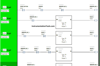
Rung 0000:
Start/Stop PB latched with memory B3:0/0 for Motor 1.B3:0/3 is connected in series with latch memory to turn off all motors.
Rung 0001:
Start/Stop PB latched with memory B3:0/1 for Motor 2 .B3:0/0 is connected in series to turn on M2 only after M1.
Rung 0002:
Start/Stop PB latched with memory B3:0/2 for Motor 3 .B3:0/0 is connected in series to turn on M3 only after M1.
Rung 0003:
Turning on M1 when B3:0/0 turns ON
Rung 0004:
Turning on M2 when B3:0/1 turns ON
Rung 0005:
Turning on M3 when B3:0/2 turns ON
Rung 0006:
M2 and M3 outputs are connected in series to enable B3:0/3
Program Output:
When M1 turns ON,

When M1 & M2 turns ON


When the Third motor Turns ON,

Conclusion:
We can use this example to understand the programming logic in Allen Bradley PLC.
Author: Hema Sundaresan
If you liked this article, then please subscribe to our YouTube Channel for PLC and SCADA video tutorials.
You can also follow us on Facebook and Twitter to receive daily updates.
Read Next:


Thanks.
I know it’s been four years since this post of 3 motors. It seems that your third motor is not turning all out puts off.
Write the plc logic for the following conditions
There are three motor m1 m2 m3 having a separate Start and stop push button
m1 must be running before starting of m2 m3 motor
Only one motor run at time