Inst ToolsInst ToolsInst Tools
  • Courses
  • Automation
    • PLC
    • Control System
    • Safety System
    • Communication
    • Fire & Gas System
  • Instrumentation
    • Design
    • Pressure
    • Temperature
    • Flow
    • Level
    • Vibration
    • Analyzer
    • Control Valve
    • Switch
    • Calibration
    • Erection & Commissioning
  • Interview
    • Instrumentation
    • Electrical
    • Electronics
    • Practical
  • Q&A
    • Instrumentation
    • Control System
    • Electrical
    • Electronics
    • Analog Electronics
    • Digital Electronics
    • Power Electronics
    • Microprocessor
  • Request
Search
  • Books
  • Software
  • Projects
  • Process
  • Tools
  • Basics
  • Formula
  • Power Plant
  • Root Cause Analysis
  • Electrical Basics
  • Animation
  • Standards
  • 4-20 mA Course
  • Siemens PLC Course
Reading: Quiz Program Logic Using PLC Programming
Share
Notification Show More
Font ResizerAa
Inst ToolsInst Tools
Font ResizerAa
  • Courses
  • Design
  • PLC
  • Interview
  • Control System
Search
  • Courses
  • Automation
    • PLC
    • Control System
    • Safety System
    • Communication
    • Fire & Gas System
  • Instrumentation
    • Design
    • Pressure
    • Temperature
    • Flow
    • Level
    • Vibration
    • Analyzer
    • Control Valve
    • Switch
    • Calibration
    • Erection & Commissioning
  • Interview
    • Instrumentation
    • Electrical
    • Electronics
    • Practical
  • Q&A
    • Instrumentation
    • Control System
    • Electrical
    • Electronics
    • Analog Electronics
    • Digital Electronics
    • Power Electronics
    • Microprocessor
  • Request
Follow US
All rights reserved. Reproduction in whole or in part without written permission is prohibited.
Inst Tools > Blog > PLC Tutorials > Quiz Program Logic Using PLC Programming

Quiz Program Logic Using PLC Programming

Last updated: March 4, 2021 3:44 pm
Editorial Staff
PLC Tutorials
No Comments
Share
3 Min Read
SHARE

Build the ladder logic program to satisfy the condition for Quiz program logic.

Contents
PLC Quiz ProgramList of Inputs and OutputsPLC ProgrammingLadder Logic DescriptionConclusion:

PLC Quiz Program

PLC Quiz Project

There are three groups participating in quiz program. Since the people are from different age group, host is planning to give more concern/preference in pressing buzzer to smaller age group.

Any one person from School group pressed buzzer is taken as first IN input, College group is having no option and the professor group should press both buzzer at same time to check in as First IN input. Host buzzer is to reset all outputs (Lamp)

Consider,

School group buzzer named as A0, A1 and Lamp as X0

College Group buzzer named as A2 and Lamp as X1

Professor group buzzer named as A3, A4 and Lamp as X2

Host Buzzer named as A5

X0 should ON if any one of A0 or A1 is pressed.

X1 should ON when A2 is pressed

X2 should ON when both A3 and A4 are pressed

If A5 is pressed, X0, X1 and X2 should OFF.

List of Inputs and Outputs
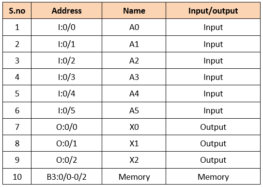
PLC Quiz Program Inputs and Outputs

PLC Programming

Quiz Program Logic Using PLC Programming
Quiz Project Using PLC Ladder Logic

Ladder Logic Description

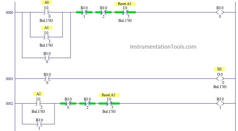
RUNG 0000

School group buzzers PB  are connected in parallel to give either option. Since buzzer is push button, latching is performed using memory coil.

Reset input is connected as normally closed switch in series to reset the output.B3:0/1 and B3:0/2 are connected as normally closed switch in series to interlock the output.

RUNG 0001

To make the condition possible, previous rung output B3:0/0  is connected to school group lamp X0.

RUNG 0002

College group buzzer PB is connected to memory coil with normally closed switch in series to reset the output. B3:0/0 and B3:0/2 are connected as normally closed switch in series to interlock the output.

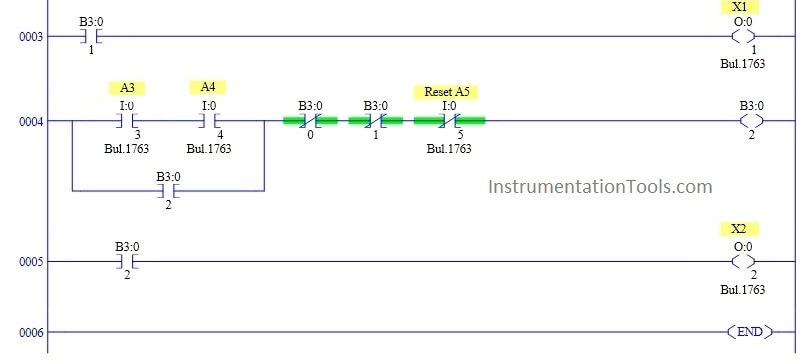
RUNG 0003

To make the condition possible, previous rung output B3:0/1 is connected to college group lamp X1.

RUNG 0004

For Professor group, both the buzzer PBs are  connected in series to memory coil with normally closed switch in series to reset the output. B3:0/0 and B3:0/1 are connected as normally closed switch in series to interlock the output.

RUNG 0005

To make the condition possible, previous rung output B3:0/2 is connected to Professor Group lamp X2.

Conclusion:

The above explained ladder logic for quiz program is for example only. We can use this example program to understand the working of Push Buttons, memory bit and Interlocking in AB PLC.

Author : Hema Sundaresan

If you liked this article, then please subscribe to our YouTube Channel for PLC and SCADA video tutorials.

You can also follow us on Facebook and Twitter to receive daily updates.

Read Next:
Electromagnetic Relay

PLC Output Types

PLC Latching Function

Relay Loop Back Circuit

PLC Ladder Diagrams

Don't Miss Our Updates
Be the first to get exclusive content straight to your email.
We promise not to spam you. You can unsubscribe at any time.
Invalid email address
You've successfully subscribed !

Continue Reading

Electric Motor Forward Reverse with Repeat Cycle PLC Logic
What is a PLC Retrofitting Project? – Importance, Procedure
PLC to Start or Stop 3 Machines using 1 Switch Program
PLC Motor Control Ladder Logic Programming
Run 4 Motors Sequentially from Same Push button PLC Program
200+ Quiz on Electrical Meters, Measurement, and Troubleshooting
Share This Article
Facebook Whatsapp Whatsapp LinkedIn Copy Link
Share
Leave a Comment

Leave a Reply Cancel reply

Your email address will not be published. Required fields are marked *

Stay Connected

128.3kFollowersLike
69.1kFollowersFollow
210kSubscribersSubscribe
38kFollowersFollow

Categories

Explore More

PLC Program for Controlling a Water Pump with 3 Power Sources
Network Switch Port Allocation Details
PLC Program for Alarm Indication in Process Control
Top PLC Manufacturers
Unknown Do’s Need to Know as a PLC Programmer
PLC Programming for Loss in Weight Liquid Systems
PLC Programming for Multi-Color Sorting Conveyor System
PLC based Gas Detection System using Ladder Logic Project

Keep Learning

Two Hand Press PLC

Two Hand Press Safety Control Circuit

Structured Text in PLC: Parking Information Systems

Structured Text in PLC: Parking Information Systems

PLC Question Bank

PLC Question Bank

Steps in PLC System Design

Steps in PLC System Design

Control System Basic Wiring Practice Animation

PLC Connection between Instrument, Junction Box, Marshalling & System Cabinet

How to Safely Design Automation System for Hazardous Environments?

Automation System for Hazardous Environments

Automatic Box Filling System using PLC Programming

Automatic Box Filling System using PLC Programming

Principle of Operation of PLC

Principle of Operation of PLC

Learn More

Instrumentation loop Diagram

Instrumentation Loop Diagrams

PLC Logic to identify empty bottles in Packing

Automatic Empty Bottle detection using PLC Logic

Siemens PLC Simulator and Plant Simulation Software

How to use Simulator in Siemens PLC?

Control Valve Direction of Control Action

PID Controller Action : Directing Acting & Reverse Acting

PlantPAx Select Add components into Project

How to Import PlantPAx Library?

Needle Valve Body Design

What is Needle Valve ?

What is a Load Cell

What is a Load Cell ?

Voltage and Current Phase Relationships in an Inductive Circuit

Voltage and Current Phase Relationships in an Inductive Circuit

Menu

  • About
  • Privacy Policy
  • Copyright

Quick Links

  • Learn PLC
  • Helping Hand
  • Part Time Job

YouTube Subscribe

Follow US
All rights reserved. Reproduction in whole or in part without written permission is prohibited.
Welcome Back!

Sign in to your account

Username or Email Address
Password

Lost your password?