Inst ToolsInst ToolsInst Tools
  • Ask
  • Courses
  • Videos
  • Q & A
    • Interview
      • Instrumentation
      • Electronics
      • Electrical
      • Practical Questions
    • MCQ
      • Instrumentation MCQ
      • Electrical MCQ
      • Electronics MCQ
      • Control Systems MCQ
      • Analog Electronics MCQ
      • Digital Electronics MCQ
      • Power Electronics MCQ
      • Microprocessor MCQ
      • Multiple Choice Questions
  • EE
    • Electronics
      • Electronics Q & A
      • Electronic Basics
      • Electronic Devices & Circuits
      • Electronics Animation
      • Digital Electronics
    • Electrical
      • Electrical Basics
      • Electrical Q & A
      • Power Electronics
      • Electrical Machines
      • Electrical Animation
      • Power Systems
      • Switchgear & Protection
      • Transmission & Distribution
  • Measure
    • Control Valves
    • Calibration
    • Temperature
    • Pressure
    • Flow
    • Level
    • Analyzers
    • Switches
    • Vibration
    • Solenoid Valve
  • Control
    • PLC Tutorials
    • Control Systems
    • Safety Instrumented System (SIS)
    • Communication
    • Fire & Gas System
  • More
    • Design
    • Tools
    • Animation
    • Basics
    • Formulas
    • Standards
    • TextBooks
    • Common
    • Software
    • Excel Tools
    • Erection & Commissioning
    • Process Fundamentals
    • Videos
    • Books
Search
All rights reserved. Reproduction in whole or in part without written permission is prohibited.
Reading: Voting Logic in Safety Instrumented System (SIS)
Share
Notification Show More
Font ResizerAa
Inst ToolsInst Tools
Font ResizerAa
  • Courses
  • PLC Tutorials
  • Control Systems
Search
  • Ask
  • Courses
  • Videos
  • Q & A
    • Interview
    • MCQ
  • EE
    • Electronics
    • Electrical
  • Measure
    • Control Valves
    • Calibration
    • Temperature
    • Pressure
    • Flow
    • Level
    • Analyzers
    • Switches
    • Vibration
    • Solenoid Valve
  • Control
    • PLC Tutorials
    • Control Systems
    • Safety Instrumented System (SIS)
    • Communication
    • Fire & Gas System
  • More
    • Design
    • Tools
    • Animation
    • Basics
    • Formulas
    • Standards
    • TextBooks
    • Common
    • Software
    • Excel Tools
    • Erection & Commissioning
    • Process Fundamentals
    • Videos
    • Books
Follow US
All rights reserved. Reproduction in whole or in part without written permission is prohibited.
Inst Tools > Blog > Safety Instrumented System (SIS) > Voting Logic in Safety Instrumented System (SIS)

Voting Logic in Safety Instrumented System (SIS)

Last updated: July 26, 2020 11:16 am
Editorial Staff
Safety Instrumented System (SIS)
1 Comment
Share
3 Min Read
SHARE

There are 1oo1, 1oo2, 2oo2, 2oo3 etc voting logic in the safety instrumented system architecture.

Contents
Voting LogicArticles You May Like :

The voting logic architecture usually used in the field instrument and or final control elements to reach certain Safety Integrity Level (SIL)  or to reach certain cost reduction due to platform shutdown. In general when we must use 1oo1, 1oo2, 2oo2, or 2oo3 voting logic architecture?

Voting Logic

Voting Logic in Safety Instrumented System (SIS)

As mentioned above, there are two purposes why certain voting logic architecture were chosen, first is to reach certain SIL and secondly to reach certain cost reduction due to spurious platform shutdown.

In order to determine a certain SIL requirement, a risk or process hazard analysis is used to identify all process, safety and environmental hazards, estimate their risks, and decide if that risk is tolerable. Where risk reduction is required an appropriate SIL is assigned.

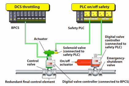
The individual components (sensor , logic solver , final elements, etc.) that are working together to implement the individual safety loops must comply with the constraints of the required SIL.

In essence, this means that all components within that loop must meet a certain Probability of Failure on Demand (PFD), Safe Failure Fraction (SFF) and Hardware Fault Tolerance (HFT) requirement for the intended SIL.

Readers are encouraged to see further detail regarding this PFDavg, SFF, and HFT in the IEC 61508 & IEC 61511.

As general rule, first of all the SIL requirement for any particular condition or application will be determined using a risk or process analysis.

After the SIL was determined then the architecture of the sensor, logic solver, and final control element is studied to investigate which architecture will fulfill the SIL requirement.

For example, if the SIL requirement for a high pressure incoming pipe line is SIL 3, then the architecture of the pressure sensor and final element will be investigated.

If 1oo1 sensor, 1oo1 logic solver, and 1oo1 shutdown valve can fulfill the SIL 3 requirement, then this architecture is chosen. If not, then any other voting logic architecture is investigated.

Let’s say after several investigations the voting logic 1oo2 sensor, 1oo2 logic solver, and 1oo2 shutdown valve can fulfill the requirement of SIL 3, then this voting logic is chosen. If the cost reduction study need to minimize spurious trip due to one of the sensor failed, then may be the sensor voting logic architecture must be upgraded to become 2oo3 architecture.

This architecture may be chosen since if one sensor failed, then the overall architecture is still fulfilling SIL 3 requirement with 1oo2 sensor configuration. Thus it doesn’t need to have a platform shutdown when one sensor failed.

Articles You May Like :

SIS Module Failure

SIS, PLC or BPCS ?

Questions on SIS

Shutdown Logic

ESDV Advantages

Don't Miss Our Updates
Be the first to get exclusive content straight to your email.
We promise not to spam you. You can unsubscribe at any time.
Invalid email address
You've successfully subscribed !
SIS Sensors
Purpose of Emergency Shutdown (ESD) System
Basic Terms used in SIL Verification
SIS Design – Safety Instrumented System
Why choose Intrinsic Safety ?
Share This Article
Facebook Whatsapp Whatsapp LinkedIn Copy Link
Share
1 Comment
  • Vivek M says:
    May 21, 2019 at 12:12 pm

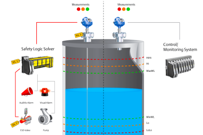
    ESD transmitters serving critical shutdown level in Safety Instrumented System are recommended to have voting logic configuration.

    Voting logic is applied to minimize the occurrence of complete loss of production caused by single transmitter fault or spurious trip shutdown. The voting configuration can be 2oo3 or 1oo2D based on SIL assessment and verification.

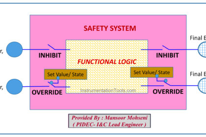
    There are some consideration when applying voting logic in the process:

    > Transmitters not to have common tapping to the process line/equipment.
    > The transmitters forming the same voting logic shall not be assigned on the same I/O module of Safety Instrumented System.
    > Each instrument cable is routed diversely.
    > Transmitters are set with the same calibration range.
    > It is also recommended to have transmitters from different manufacturer to avoid manufacturing defect causing common mode failure.

    Also on this voting logic configuration, SIS needs to compare the transmitters value and initiate alarm on Human Machine Interface (HMI) for any deviations on measurement among the transmitters.

    Reply

Leave a Reply Cancel reply

Your email address will not be published. Required fields are marked *

Stay Connected

128.3kFollowersLike
69.1kFollowersFollow
208kSubscribersSubscribe
38kFollowersFollow

Categories

Recent Comments

  • Kamli on Top Free PLC Software
  • Guifty Shimica on Top Non-PLC Certification Courses for Automation Professionals
  • Guifty Shimica on Top Non-PLC Certification Courses for Automation Professionals
  • MIHARITSOA Aina Sitraka on Top Non-PLC Certification Courses for Automation Professionals

Related Articles

Safety Instrumented System SIS Component Selection

SIS Component Selection – Safety Instrumented System

SIS PFD - Safety Instrumented System

SIS PFD – Safety Instrumented System

Component De-rating

Component De-rating in Control Systems

transmitters shared for BPCS and SIS

SIS Instrument Sharing – Transmitters Shared for BPCS and SIS Example

safety control system

Safety Instrumented Burner Management System

Intrinsic Safe Calculation

Intrinsic Safe Calculation

Failure Demand in Safety Control Circuit

Safety Instrumented System Module Failure

Maintenance Override Switch (MOS)

What is Maintenance Override Switch (MOS) ?

More Articles

PLC Programming Projects for Beginners

PLC Programming Projects for Beginners

Digital Electronics Multiple Choice Questions

Programmable Array Logic Objective Questions

Difference between SIS, PLC and BPCS Systems

Difference between SIS, PLC and BPCS Systems

Induction Motor Operating Characteristics

Voltage Divider Rule

Voltage Divider Rule

Types of PLC

#14 PLC Best Practices – Restrict Third-party Data Interfaces

Armature Current in a DC Motor

DC Motor Torque

Why Restriction Orifice is some distance from Blowdown valve

Why Restriction Orifice is some distance from Blowdown valve ?

Follow US
All rights reserved. Reproduction in whole or in part without written permission is prohibited.
Welcome Back!

Sign in to your account

Username or Email Address
Password

Lost your password?