Inst ToolsInst ToolsInst Tools
  • Ask
  • Courses
  • Videos
  • Q & A
    • Interview
      • Instrumentation
      • Electronics
      • Electrical
      • Practical Questions
    • MCQ
      • Instrumentation MCQ
      • Electrical MCQ
      • Electronics MCQ
      • Control Systems MCQ
      • Analog Electronics MCQ
      • Digital Electronics MCQ
      • Power Electronics MCQ
      • Microprocessor MCQ
      • Multiple Choice Questions
  • EE
    • Electronics
      • Electronics Q & A
      • Electronic Basics
      • Electronic Devices & Circuits
      • Electronics Animation
      • Digital Electronics
    • Electrical
      • Electrical Basics
      • Electrical Q & A
      • Power Electronics
      • Electrical Machines
      • Electrical Animation
      • Power Systems
      • Switchgear & Protection
      • Transmission & Distribution
  • Measure
    • Control Valves
    • Calibration
    • Temperature
    • Pressure
    • Flow
    • Level
    • Analyzers
    • Switches
    • Vibration
    • Solenoid Valve
  • Control
    • PLC Tutorials
    • Control Systems
    • Safety Instrumented System (SIS)
    • Communication
    • Fire & Gas System
  • More
    • Design
    • Tools
    • Animation
    • Basics
    • Formulas
    • Standards
    • TextBooks
    • Common
    • Software
    • Excel Tools
    • Erection & Commissioning
    • Process Fundamentals
    • Videos
    • Books
Search
All rights reserved. Reproduction in whole or in part without written permission is prohibited.
Reading: Safety Instrumented System Module Failure
Share
Notification Show More
Font ResizerAa
Inst ToolsInst Tools
Font ResizerAa
  • Courses
  • PLC Tutorials
  • Control Systems
Search
  • Ask
  • Courses
  • Videos
  • Q & A
    • Interview
    • MCQ
  • EE
    • Electronics
    • Electrical
  • Measure
    • Control Valves
    • Calibration
    • Temperature
    • Pressure
    • Flow
    • Level
    • Analyzers
    • Switches
    • Vibration
    • Solenoid Valve
  • Control
    • PLC Tutorials
    • Control Systems
    • Safety Instrumented System (SIS)
    • Communication
    • Fire & Gas System
  • More
    • Design
    • Tools
    • Animation
    • Basics
    • Formulas
    • Standards
    • TextBooks
    • Common
    • Software
    • Excel Tools
    • Erection & Commissioning
    • Process Fundamentals
    • Videos
    • Books
Follow US
All rights reserved. Reproduction in whole or in part without written permission is prohibited.
Inst Tools > Blog > Instrumentation Design > Safety Instrumented System Module Failure

Safety Instrumented System Module Failure

Last updated: May 21, 2019 2:40 pm
Editorial Staff
Instrumentation Design Safety Instrumented System (SIS)
3 Comments
Share
3 Min Read
SHARE

The international standard IEC/EN 61508 has been widely accepted as the basis for the specification, design and operation of safety instrumented systems (SIS).

Contents
Safety Instrumented System Module FailureArticles You May Like :SIS Engineer QuestionsAlarm and Trip SystemsProcess Control SystemInstrumentation ControlFunctional Safety Questions

As the basic standard, IEC/EN 61508 uses a formulation based on risk assessment: An assessment of the risk is undertaken and on the basis of this the necessary Safety Integrity Level (SIL) is determined for components and systems with safety functions.

SIL-evaluated components and systems are intended to reduce the risk associated with a device to a justifiable level or “tolerable risk”.

Safety Instrumented System Module Failure

To categorise the safety integrity of a safety function the probability of failure is considered – in effect the inverse of the SIL definition, looking at failure to perform rather than success.

It is easier to identify and quantify possible conditions and causes leading to failure of a safety function than it is to guarantee the desired action of a safety function when called upon.

Two classes of SIL are identified, depending on the service provided by the safety function.

  • For safety functions that are activated when required (on demand mode) the probability of failure to perform correctly is given, whilst
  • for safety functions that are in place continuously the probability of a dangerous failure is expressed in terms of a given period of time (per hour)(continuous mode).

In summary, IEC/EN 61508 requires that when safety functions are to be performed as specified in terms of a safety integrity level.

The probabilities of failure are also considered in safety integrity levels, as shown

Safety Instrumented System Failure

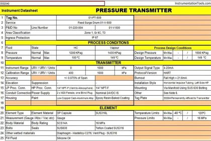
The PFD value (Probability of Failure on Demand) is the probability of failure of a unit as a component part of a complete safety system in the low demand mode.

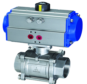
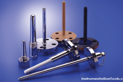
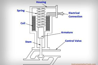
The PFD value for the complete safety related function is derived from the values of individual components. Sensor and actuator are fitted in the field, leading to exposed and physical stress factors (process medium, pressure, temperature, vibration, etc.).

Safety Instrumented System Modules

The risk of failure associated with these components is thus relatively high. 25 % of the entire PFD should be therefore reserved for the sensor, 40 % for the actuator.

15 % remains for the fail-safe control, and 10 % for each of the interface modules (interface modules and the control system have no contact with the process medium and are located in protected switch rooms).

Articles You May Like :

SIS Engineer Questions

Alarm and Trip Systems

Process Control System

Instrumentation Control

Functional Safety Questions

Don't Miss Our Updates
Be the first to get exclusive content straight to your email.
We promise not to spam you. You can unsubscribe at any time.
Invalid email address
You've successfully subscribed !
5 Most Common Mistakes When Specifying Valves
Instruments Tapping Points – Common versus Individual
Floating Vs. Grounded Voltage
Steam Tracing
Design and Implement Motor Control – Electrical Engineering
Share This Article
Facebook Whatsapp Whatsapp LinkedIn Copy Link
Share
3 Comments
  • Jokor says:
    December 8, 2016 at 6:17 am

    Please give us analysis on the below two questions
    What is the significant use of SIS supporting tools in the SIS design stage?
    What are the already available SIS supporting tools and what is their main functionality?

    Reply
    • S Bharadwaj Reddy says:
      December 9, 2016 at 8:16 am

      You might check out http://www.sissuite.com.

      Reply
  • Florent Brissaud says:
    December 9, 2016 at 3:29 am

    Hi!
    There is a confusion in your following text: “for safety function that are in place continuously the probability of a dangerous failure is expressed in terms of a given period of time (per hour)”.

    A probability is never expressed per time unit. A probability is unitless.
    In a continous mode, the used criteria (PFH) is a frequency of failure and not a probability. By the way, the wrong term “probability of failure per hour” does not appear anymore in the second edition of the IEC 61508, because it was inappropriate.
    Regards

    Reply

Leave a Reply Cancel reply

Your email address will not be published. Required fields are marked *

Stay Connected

128.3kFollowersLike
69.1kFollowersFollow
208kSubscribersSubscribe
38kFollowersFollow

Categories

Recent Comments

  • Kamli on Top Free PLC Software
  • Guifty Shimica on Top Non-PLC Certification Courses for Automation Professionals
  • Guifty Shimica on Top Non-PLC Certification Courses for Automation Professionals
  • MIHARITSOA Aina Sitraka on Top Non-PLC Certification Courses for Automation Professionals

Related Articles

Thermowell Design Guidelines

Intrinsic Barrier

Why choose Intrinsic Safety ?

Instrument Heat Trace

Electrical Heat Tracing

Emerson ASCO Solenoid valve references

SIS Solenoid Valves – Safety PLC

Vendor Selection in Procurement Service Cycle (For Industrial Projects)

Compliance Table Application (for Procurement Service Cycle)

Diaphragm Seal Material Selection

Diaphragm Seal Material Selection

Tagging Philosophy for Junction Box

Tagging Philosophy for Junction Box, Cable, and Cable Drum

Process Variable Damping Graph

Process Variable Damping of Transmitter

More Articles

Bubble Tube Level measurement

Bubble Tube Level Measurement Principle

Convert an Electrical Diagram into PLC Program

How to Convert an Electrical Diagram into PLC Program?

What is an Orifice Flange ?

What is an Orifice Flange? – Purpose and Applications

Digital Electronics Multiple Choice Questions

Random Access Memory Objective Questions – Part 4

PLC Programming Sequence Logic

PLC Programming to Control Lights in a Sequence

Typical process control loop

How Process Control Loop Works

Electrical Machines Objective Questions

Electrical Machines MCQ Series 7

single-acting-vs-double-acting-control-valve-actuators

Single Acting Vs Double Acting Actuators

Follow US
All rights reserved. Reproduction in whole or in part without written permission is prohibited.
Welcome Back!

Sign in to your account

Username or Email Address
Password

Lost your password?