Inst ToolsInst ToolsInst Tools
  • Courses
  • Automation
    • PLC
    • Control System
    • Safety System
    • Communication
    • Fire & Gas System
  • Instrumentation
    • Design
    • Pressure
    • Temperature
    • Flow
    • Level
    • Vibration
    • Analyzer
    • Control Valve
    • Switch
    • Calibration
    • Erection & Commissioning
  • Interview
    • Instrumentation
    • Electrical
    • Electronics
    • Practical
  • Q&A
    • Instrumentation
    • Control System
    • Electrical
    • Electronics
    • Analog Electronics
    • Digital Electronics
    • Power Electronics
    • Microprocessor
  • Request
Search
  • Books
  • Software
  • Projects
  • Process
  • Tools
  • Basics
  • Formula
  • Power Plant
  • Root Cause Analysis
  • Electrical Basics
  • Animation
  • Standards
  • 4-20 mA Course
  • Siemens PLC Course
Reading: Moving Iron Vane Meter Movement
Share
Font ResizerAa
Inst ToolsInst Tools
Font ResizerAa
  • Courses
  • Design
  • PLC
  • Interview
  • Control System
Search
  • Courses
  • Automation
    • PLC
    • Control System
    • Safety System
    • Communication
    • Fire & Gas System
  • Instrumentation
    • Design
    • Pressure
    • Temperature
    • Flow
    • Level
    • Vibration
    • Analyzer
    • Control Valve
    • Switch
    • Calibration
    • Erection & Commissioning
  • Interview
    • Instrumentation
    • Electrical
    • Electronics
    • Practical
  • Q&A
    • Instrumentation
    • Control System
    • Electrical
    • Electronics
    • Analog Electronics
    • Digital Electronics
    • Power Electronics
    • Microprocessor
  • Request
Follow US
All rights reserved. Reproduction in whole or in part without written permission is prohibited.
Inst Tools > Blog > Electrical Theory > Moving Iron Vane Meter Movement

Moving Iron Vane Meter Movement

Last updated: August 7, 2018 5:53 pm
Editorial Staff
Electrical Theory
No Comments
Share
2 Min Read
SHARE

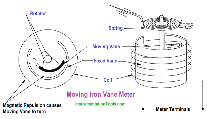
The moving iron vane movement (Figure 1) can be used to measure both AC current and voltage. By changing the meter scale calibration, the movement can be used to measure DC current and voltage. The moving iron vane meter operates on the principle of magnetic repulsion between like poles.

The measured current flows through a field coil which produces a magnetic field proportional to the magnitude of current. Suspended in this field are two iron vanes attached to a pointer.

Moving Iron Vane Meter Movement

Figure 1 : Moving Iron Vane Meter Movement

The two iron vanes consist of one fixed and one movable vane. The magnetic field produced by the current flow magnetizes the two iron vanes with the same polarity regardless of the direction of current through the coil. Since like poles repel one another, the moving iron vane pulls away from the fixed vane and moves the meter pointer.

This motion exerts a force against a spring. The distance the moving iron vane will travel against the spring depends on the strength of the magnetic field. The strength of the magnetic field depends on the magnitude of current flow.

As stated previously, this type of meter movement may also be used to measure voltage. When this type of movement is used to measure voltage, the field coil consists of many turns of fine wire used to generate a strong magnetic field with only a small current flow.
Don't Miss Our Updates
Be the first to get exclusive content straight to your email.
We promise not to spam you. You can unsubscribe at any time.
Invalid email address
You've successfully subscribed !

Continue Reading

3-Wire, Three-Phase Delta Wiring System
Circuit Breaker Control Circuit
Batteries
Low Voltage Air Circuit Breaker Principle
Magnetic Circuits
DC Circuit Analysis Loop Equations
Share This Article
Facebook Whatsapp Whatsapp LinkedIn Copy Link
Share
Leave a Comment

Leave a Reply Cancel reply

Your email address will not be published. Required fields are marked *

Stay Connected

128.3kFollowersLike
69.1kFollowersFollow
210kSubscribersSubscribe
38kFollowersFollow

Categories

Explore More

Voltage Divider
Inductive Time Constant
Three Phase Systems
Electric Circuit : Open & Short Circuits
Parallel Circuit Current Calculations
Electrical Diagrams and Schematics
DC Machines Terminology
DC Generator

Keep Learning

AC generator Voltage Regulators

AC Generator Voltage Regulators

Types of Batteries

Types of Batteries

Synchronous Motor Principle

Synchronous Motors

Block Diagram

Block Diagram

Total Resistance in a Parallel Circuit

Resistance in Parallel Circuits

Parallel Circuit Unknown Resistance

Simplified Formulas for Parallel Circuit Resistance Calculations

Shunt-Wound DC Motor

Shunt-Wound Motor Operation

Single Line Diagram

Single Line Diagram

Learn More

How to Connect HART Communicator with DP Transmitter

15 HART Communicator Questions

Smart Transmitter Calibration Tutorial Part 3

Smart Transmitter Calibration Tutorial Part 3

Level Gauge Interface Measurement

Level Gauge Interface & Temperature Problems

Functional Block Diagram PLC Example for Traffic Light System

Functional Block Diagram PLC Example for Traffic Light System

Types of Control Valve Trim

Types of Control Valve Trim

Modbus scan

How Modbus Communication works

Parts of Steam Ejector

Working Principle of Steam Ejector

Digital Electronics Multiple Choice Questions

Transistor Transistor Logic (TTL) Objective Questions

Menu

  • About
  • Privacy Policy
  • Copyright

Quick Links

  • Learn PLC
  • Helping Hand
  • Part Time Job

YouTube Subscribe

Follow US
All rights reserved. Reproduction in whole or in part without written permission is prohibited.
Welcome Back!

Sign in to your account

Username or Email Address
Password

Lost your password?