Inst ToolsInst ToolsInst Tools
  • Ask
  • Courses
  • Videos
  • Q & A
    • Interview
      • Instrumentation
      • Electronics
      • Electrical
      • Practical Questions
    • MCQ
      • Instrumentation MCQ
      • Electrical MCQ
      • Electronics MCQ
      • Control Systems MCQ
      • Analog Electronics MCQ
      • Digital Electronics MCQ
      • Power Electronics MCQ
      • Microprocessor MCQ
      • Multiple Choice Questions
  • EE
    • Electronics
      • Electronics Q & A
      • Electronic Basics
      • Electronic Devices & Circuits
      • Electronics Animation
      • Digital Electronics
    • Electrical
      • Electrical Basics
      • Electrical Q & A
      • Power Electronics
      • Electrical Machines
      • Electrical Animation
      • Power Systems
      • Switchgear & Protection
      • Transmission & Distribution
  • Measure
    • Control Valves
    • Calibration
    • Temperature
    • Pressure
    • Flow
    • Level
    • Analyzers
    • Switches
    • Vibration
    • Solenoid Valve
  • Control
    • PLC Tutorials
    • Control Systems
    • Safety Instrumented System (SIS)
    • Communication
    • Fire & Gas System
  • More
    • Design
    • Tools
    • Animation
    • Basics
    • Formulas
    • Standards
    • TextBooks
    • Common
    • Software
    • Excel Tools
    • Erection & Commissioning
    • Process Fundamentals
    • Videos
    • Books
Search
All rights reserved. Reproduction in whole or in part without written permission is prohibited.
Reading: Transformer Theory of Operation
Share
Notification Show More
Font ResizerAa
Inst ToolsInst Tools
Font ResizerAa
  • Courses
  • PLC Tutorials
  • Control Systems
Search
  • Ask
  • Courses
  • Videos
  • Q & A
    • Interview
    • MCQ
  • EE
    • Electronics
    • Electrical
  • Measure
    • Control Valves
    • Calibration
    • Temperature
    • Pressure
    • Flow
    • Level
    • Analyzers
    • Switches
    • Vibration
    • Solenoid Valve
  • Control
    • PLC Tutorials
    • Control Systems
    • Safety Instrumented System (SIS)
    • Communication
    • Fire & Gas System
  • More
    • Design
    • Tools
    • Animation
    • Basics
    • Formulas
    • Standards
    • TextBooks
    • Common
    • Software
    • Excel Tools
    • Erection & Commissioning
    • Process Fundamentals
    • Videos
    • Books
Follow US
All rights reserved. Reproduction in whole or in part without written permission is prohibited.
Inst Tools > Blog > Electrical Theory > Transformer Theory of Operation

Transformer Theory of Operation

Last updated: August 6, 2018 10:45 pm
Editorial Staff
Electrical Theory
1 Comment
Share
2 Min Read
SHARE

A transformer works on the principle that energy can be transferred by magnetic induction from one set of coils to another set by means of a varying magnetic flux. The magnetic flux is produced by an AC source.

The coil of a transformer that is energized from an AC source is called the primary winding (coil), and the coil that delivers this AC to the load is called the secondary winding (coil) (Figure 1).

In Figure 1, the primary and secondary coils are shown on separate legs of the magnetic circuit so that we can easily understand how the transformer works. Actually, half of the primary and secondary coils are wound on each of the two legs, with sufficient insulation between the two coils and the core to properly insulate the windings from one another and the core.

Core-Type Transformer

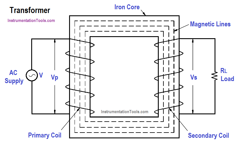
Figure 1 : Core-Type Transformer

A transformer wound, such as in Figure 1, will operate at a greatly reduced efficiency due to the magnetic leakage. Magnetic leakage is the part of the magnetic flux that passes through either one of the coils, but not through both. The larger the distance between the primary and secondary windings, the longer the magnetic circuit and the greater the leakage.

When alternating voltage is applied to the primary winding, an alternating current will flow that will magnetize the magnetic core, first in one direction and then in the other direction. This alternating flux flowing around the entire length of the magnetic circuit induces a voltage in both the primary and secondary windings.

Transformer Efficiency

Since both windings are linked by the same flux, the voltage induced per turn of the primary and secondary windings must be the same value and same direction. This voltage opposes the voltage applied to the primary winding and is called counter-electromotive force (CEMF).

Don't Miss Our Updates
Be the first to get exclusive content straight to your email.
We promise not to spam you. You can unsubscribe at any time.
Invalid email address
You've successfully subscribed !
Parallel Circuit
What is a circuit breaker ?
DC Generator Internal Losses
Moving Iron Vane Meter Movement
Electrical Wiring Terminology
Share This Article
Facebook Whatsapp Whatsapp LinkedIn Copy Link
Share
1 Comment
  • Saba says:
    July 27, 2022 at 5:27 pm

    how to do fault isolation of transformer. Kindly guide.

    Reply

Leave a Reply Cancel reply

Your email address will not be published. Required fields are marked *

Stay Connected

128.3kFollowersLike
69.1kFollowersFollow
208kSubscribersSubscribe
38kFollowersFollow

Categories

Recent Comments

  • Kamli on Top Free PLC Software
  • Guifty Shimica on Top Non-PLC Certification Courses for Automation Professionals
  • Guifty Shimica on Top Non-PLC Certification Courses for Automation Professionals
  • MIHARITSOA Aina Sitraka on Top Non-PLC Certification Courses for Automation Professionals

Related Articles

Inductive Time Constant

Inductive Time Constant

Calculate Power in Series RCL Circuit

Calculate Power in Series RCL Circuit

AC to DC Conversion with a Commutator

DC Machines Terminology

Shunt-Wound DC Generator Principle

Shunt-Wound DC Generators

Series Parallel Circuit Analysis

Series – Parallel Circuit Analysis

Gang Switch Principle

Reading Electrical Schematics

Ohm Meter Circuit

Ohm Meter

Left-Hand Rule for Generators

Starting of DC Motors

More Articles

PLC Program for Food Processing

PLC Program for Food Processing Industry

Types of Digital Outputs in PLC

Types of Digital Outputs in PLC

Liquid Level Switch Control Pump and Lamp

Liquid Level Switch Control Pump and Lamp

Electrical Machines Questions and Answers

Polyphase Induction Motors Quiz

RF and RTJ Flange Installed Gasket

Flange Joint Errors shutdowns root cause analyzed and eliminated

Surface Condenser Condensate Evacuation Pumps

Condensate Pump Frequent Wrecks Threatens Long Plant Outages

Density-Measurement-using-DP-Transmitter-for-open-tank

Density Measurement for Open Tank with Constant Level Application

Power Electronics Objective Questions

Pulse Width Modulation Inverters Questions

Follow US
All rights reserved. Reproduction in whole or in part without written permission is prohibited.
Welcome Back!

Sign in to your account

Username or Email Address
Password

Lost your password?