Inst ToolsInst ToolsInst Tools
  • Courses
  • Videos
  • Q & A
    • Interview
      • Instrumentation
      • Electronics
      • Electrical
      • Practical Questions
    • MCQ
      • Instrumentation MCQ
      • Electrical MCQ
      • Electronics MCQ
      • Control Systems MCQ
      • Analog Electronics MCQ
      • Digital Electronics MCQ
      • Power Electronics MCQ
      • Microprocessor MCQ
      • Multiple Choice Questions
  • EE
    • Electronics
      • Electronics Q & A
      • Electronic Basics
      • Electronic Devices & Circuits
      • Electronics Animation
      • Digital Electronics
    • Electrical
      • Electrical Basics
      • Electrical Q & A
      • Power Electronics
      • Electrical Machines
      • Electrical Animation
      • Power Systems
      • Switchgear & Protection
      • Transmission & Distribution
  • Measure
    • Control Valves
    • Calibration
    • Temperature
    • Pressure
    • Flow
    • Level
    • Analyzers
    • Switches
    • Vibration
    • Solenoid Valve
  • Control
    • PLC Tutorials
    • Control Systems
    • Safety Instrumented System (SIS)
    • Communication
    • Fire & Gas System
  • More
    • Design
    • Tools
    • Animation
    • Basics
    • Formulas
    • Standards
    • TextBooks
    • Common
    • Software
    • Excel Tools
    • Erection & Commissioning
    • Process Fundamentals
    • Videos
    • Books
Search
All rights reserved. Reproduction in whole or in part without written permission is prohibited.
Reading: Shunt-Wound DC Generators
Share
Notification Show More
Font ResizerAa
Inst ToolsInst Tools
Font ResizerAa
  • Courses
  • PLC Tutorials
  • Control Systems
Search
  • Courses
  • Videos
  • Q & A
    • Interview
    • MCQ
  • EE
    • Electronics
    • Electrical
  • Measure
    • Control Valves
    • Calibration
    • Temperature
    • Pressure
    • Flow
    • Level
    • Analyzers
    • Switches
    • Vibration
    • Solenoid Valve
  • Control
    • PLC Tutorials
    • Control Systems
    • Safety Instrumented System (SIS)
    • Communication
    • Fire & Gas System
  • More
    • Design
    • Tools
    • Animation
    • Basics
    • Formulas
    • Standards
    • TextBooks
    • Common
    • Software
    • Excel Tools
    • Erection & Commissioning
    • Process Fundamentals
    • Videos
    • Books
Follow US
All rights reserved. Reproduction in whole or in part without written permission is prohibited.
Inst Tools > Blog > Electrical Theory > Shunt-Wound DC Generators

Shunt-Wound DC Generators

Last updated: July 28, 2018 12:06 pm
Editorial Staff
Electrical Theory
No Comments
Share
2 Min Read
SHARE

When the field winding of a generator is connected in parallel with the generator armature, the generator is called a shunt-wound generator (Figure 8).

Shunt-Wound DC Generator

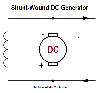
Figure 8a : Shunt-Wound DC Generator

The excitation current in a shunt-wound generator is dependent upon the output voltage and the field resistance. Normally, field excitation is maintained between 0.5 and 5 percent of the total current output of the generator.

Shunt-Wound DC Generator Principle

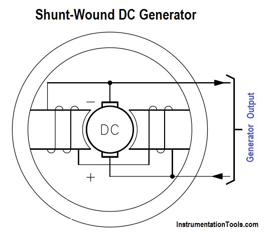
Figure 8 b : Shunt-Wound DC Generator

The shunt-wound generator, running at a constant speed under varying load conditions, has a much more stable voltage output than does a series-wound generator. Some change in output voltage does take place. This change is caused by the fact that, as the load current increases, the voltage drop (IaRa) across the armature coil increases, causing output voltage to decrease.

Voltage-vs-Load Current for Shunt-Wound DC Generator

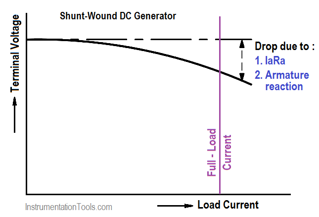
Figure 9 : Output Voltage-vs-Load Current for Shunt-Wound DC Generator

As a result, the current through the field decreases, reducing the magnetic field and causing voltage to decrease even more. If load current is much higher than the design of the generator, the drop in output voltage is severe. For load current within the design range of the generator, the drop in output voltage is minimal (Figure 9).

Don't Miss Our Updates
Be the first to get exclusive content straight to your email.
We promise not to spam you. You can unsubscribe at any time.
Invalid email address
You've successfully subscribed !

Continue Reading

4-Wire, Three-Phase Wye Wiring System
Transformer Losses and Efficiency
Three Phase AC Generators
Circuit Breaker Control Circuit
Electrical Symbols
Calculate Power in Parallel RC Circuit
Share This Article
Facebook Whatsapp Whatsapp LinkedIn Copy Link
Share
Leave a Comment

Leave a Reply Cancel reply

Your email address will not be published. Required fields are marked *

Stay Connected

128.3kFollowersLike
69.1kFollowersFollow
208kSubscribersSubscribe
38kFollowersFollow

Categories

Explore More

Applying Kirchhoff’s Voltage Law
Synchronous Motors
Capacitor
Ohm Meter
D’Arsonval Meter Movement
Full-Wave Rectifier Circuit
Half-Wave Rectifier Circuit
Schematic Diagram
Rectifiers, Forward Bias and Reverse Bias
Parallel Circuit

Keep Learning

Inductive Time Constant

Inductive Time Constant

Types of Fuses

Electrical System Components and Protection Devices

Generator Action in a Motor

What is Synchroscope ?

Wiring Diagram

Wiring Diagram

Generator Action in a Motor

Generator Action in a Motor

Core-Type Transformer

Transformer Theory of Operation

Measuring Circuit Voltage

Voltmeters

Parallel RLC Circuit

Impedance in RLC Circuits

Discover More

Pressurizer

Pressurizer

Basic Power Electronics Interview Questions

Basic Power Electronics Interview Questions

Erratic Radar Level Gauges

Erratic Radar Level Gauges Delays a Refinery Commissioning

Cable Gland Parts

What is a Cable Gland ?

Power Systems Questions & Answers

Power Systems MCQ Series 9

Thermowell Problems

Thermowell Problems

Comparison of MOSFET and BJT

Comparison of MOSFET and BJT

Power Systems Questions & Answers

Power Systems MCQ Series 8

Follow US
All rights reserved. Reproduction in whole or in part without written permission is prohibited.
Welcome Back!

Sign in to your account

Username or Email Address
Password

Lost your password?