Inst ToolsInst ToolsInst Tools
  • Courses
  • Automation
    • PLC
    • Control System
    • Safety System
    • Communication
    • Fire & Gas System
  • Instrumentation
    • Design
    • Pressure
    • Temperature
    • Flow
    • Level
    • Vibration
    • Analyzer
    • Control Valve
    • Switch
    • Calibration
    • Erection & Commissioning
  • Interview
    • Instrumentation
    • Electrical
    • Electronics
    • Practical
  • Q&A
    • Instrumentation
    • Control System
    • Electrical
    • Electronics
    • Analog Electronics
    • Digital Electronics
    • Power Electronics
    • Microprocessor
  • Request
Search
  • Books
  • Software
  • Projects
  • Process
  • Tools
  • Basics
  • Formula
  • Power Plant
  • Root Cause Analysis
  • Electrical Basics
  • Animation
  • Standards
  • 4-20 mA Course
  • Siemens PLC Course
Reading: Voltage Divider
Share
Font ResizerAa
Inst ToolsInst Tools
Font ResizerAa
  • Courses
  • Design
  • PLC
  • Interview
  • Control System
Search
  • Courses
  • Automation
    • PLC
    • Control System
    • Safety System
    • Communication
    • Fire & Gas System
  • Instrumentation
    • Design
    • Pressure
    • Temperature
    • Flow
    • Level
    • Vibration
    • Analyzer
    • Control Valve
    • Switch
    • Calibration
    • Erection & Commissioning
  • Interview
    • Instrumentation
    • Electrical
    • Electronics
    • Practical
  • Q&A
    • Instrumentation
    • Control System
    • Electrical
    • Electronics
    • Analog Electronics
    • Digital Electronics
    • Power Electronics
    • Microprocessor
  • Request
Follow US
All rights reserved. Reproduction in whole or in part without written permission is prohibited.
Inst Tools > Blog > Electrical Theory > Voltage Divider

Voltage Divider

Last updated: July 23, 2018 2:25 pm
Editorial Staff
Electrical Theory
No Comments
Share
1 Min Read
SHARE

A voltage divider, or network, is used when it is necessary to obtain different values of voltage from a single energy source. A simple voltage divider is shown in Figure 29.

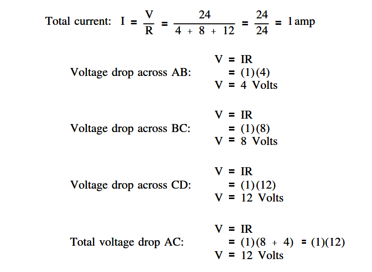
In this circuit, 24 volts is applied to three resistors in series. The total resistance limits the current through the circuit to one ampere. Individual voltages are found as follows using below equation.

Voltage Divider

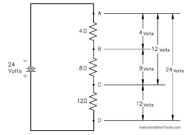
Figure 29 Voltage Divider

Voltage Divider Equation

Don't Miss Our Updates
Be the first to get exclusive content straight to your email.
We promise not to spam you. You can unsubscribe at any time.
Invalid email address
You've successfully subscribed !

Continue Reading

Parallel Circuit
Transformer Turns Ratio
Transformer Losses and Efficiency
Full-Wave Rectifier Circuit
Single Phase AC Induction Motors
AC Induction Motor Slip
Share This Article
Facebook Whatsapp Whatsapp LinkedIn Copy Link
Share
Leave a Comment

Leave a Reply Cancel reply

Your email address will not be published. Required fields are marked *

Stay Connected

128.3kFollowersLike
69.1kFollowersFollow
210kSubscribersSubscribe
38kFollowersFollow

Categories

Explore More

DC Motor Theory
Transformer Impedance Ratio
DC Generator Theory
Capacitance and Capacitive Reactance
Starting of DC Motors
Losses in AC Generator
AC Generator Nameplate Ratings
D’Arsonval Meter Movement

Keep Learning

DC Motor Action

DC Motor Speed

4-Wire, Three-Phase Delta Wiring System

4-Wire, Three-Phase Delta Wiring System

Phase angle

AC Generation Analysis : Effective Values, Phase Angle and Frequency

Electrical Component Symbols

Electrical Diagrams and Schematics

Resistor Y and Delta Network Calculation

Y and Delta Resistor Network Calculations

Inductor Principle

Inductance and Inductive Reactance

Electrical Wiring Terminology

Electrical Wiring Terminology

Wattmeter Principle

Wattmeter

Learn More

What is a Servo Valve?

What is a Servo Valve? – Principle and Advantages

Closed-tank-DP-Level-Transmitter-with-wet-leg-Zero-elevation-Calibration

Closed tank DP Level Transmitter with wet leg Zero elevation Calibration

Integral controller eliminates offset error

How Integral Controller Reduces offset error ?

Pneumatic Transmitter

Questions on Pneumatic Transmitter and Repeater

How are Data Centers Cooled

How are Data Centers Cooled?

Tanks Draining Control in PLC using Functional Block Diagram

Tanks Draining Control in PLC using Functional Block Diagram

Electrical Machines Objective Questions

Electrical Machines MCQ Series 11

Ziegler-Nichols Open Loop Tuning Procedure

Ziegler-Nichols Open Loop Tuning Procedure

Menu

  • About
  • Privacy Policy
  • Copyright

Quick Links

  • Learn PLC
  • Helping Hand
  • Part Time Job

YouTube Subscribe

Follow US
All rights reserved. Reproduction in whole or in part without written permission is prohibited.
Welcome Back!

Sign in to your account

Username or Email Address
Password

Lost your password?