Inst ToolsInst ToolsInst Tools
  • Courses
  • Automation
    • PLC
    • Control System
    • Safety System
    • Communication
    • Fire & Gas System
  • Instrumentation
    • Design
    • Pressure
    • Temperature
    • Flow
    • Level
    • Vibration
    • Analyzer
    • Control Valve
    • Switch
    • Calibration
    • Erection & Commissioning
  • Interview
    • Instrumentation
    • Electrical
    • Electronics
    • Practical
  • Q&A
    • Instrumentation
    • Control System
    • Electrical
    • Electronics
    • Analog Electronics
    • Digital Electronics
    • Power Electronics
    • Microprocessor
Search
  • Books
  • Software
  • Projects
  • Process
  • Tools
  • Basics
  • Formula
  • Power Plant
  • Root Cause Analysis
  • Electrical Basics
  • Animation
  • Standards
  • 4-20 mA Course
  • Siemens PLC Course
Reading: Simplified Formulas for Parallel Circuit Resistance Calculations
Share
Notification Show More
Font ResizerAa
Inst ToolsInst Tools
Font ResizerAa
  • Courses
  • Design
  • PLC
  • Interview
  • Control System
Search
  • Courses
  • Automation
    • PLC
    • Control System
    • Safety System
    • Communication
    • Fire & Gas System
  • Instrumentation
    • Design
    • Pressure
    • Temperature
    • Flow
    • Level
    • Vibration
    • Analyzer
    • Control Valve
    • Switch
    • Calibration
    • Erection & Commissioning
  • Interview
    • Instrumentation
    • Electrical
    • Electronics
    • Practical
  • Q&A
    • Instrumentation
    • Control System
    • Electrical
    • Electronics
    • Analog Electronics
    • Digital Electronics
    • Power Electronics
    • Microprocessor
Follow US
All rights reserved. Reproduction in whole or in part without written permission is prohibited.
Inst Tools > Blog > Electrical Theory > Simplified Formulas for Parallel Circuit Resistance Calculations

Simplified Formulas for Parallel Circuit Resistance Calculations

Last updated: July 23, 2018 2:11 pm
Editorial Staff
Electrical Theory
2 Comments
Share
2 Min Read
SHARE

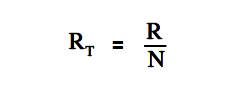
Total resistance of equal resistors in a parallel circuit is equal to the resistance of one resistor divided by the number of resistors.

Total resistance of equal resistors in a parallel circuit

where
RT = total resistance
R = resistance of one resistor
N = number of resistors

Example:

Five lamps, each with a resistance of 40Ω, are connected in parallel. Find total resistance.

Solution :

R1 = R2 = R3 = R4 = R5 = 40Ω

So, N = 5

Total resistance of equal resistors in a parallel circuit

RT = R / N = 40/5 = 8 Ω

When any two resistors are unequal in a parallel circuit, it is easier to calculate RT by multiplying the two resistances and then dividing the product by the sum, as shown in below equation.

Parallel circuit Two resistors Formula

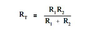
Above equation, this is valid when there are only two resistors in parallel.

Example:

Find the total resistance of a parallel circuit which has one 12Ω and one 4Ω resistor.

Solution :

Parallel circuit Two resistors Formula

RT = (12 x 4) / (12+4) = 48/16 = 3 Ω

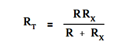
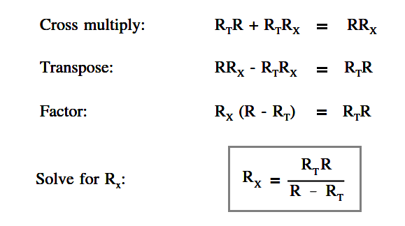
In certain cases involving two resistors in parallel, it is useful to find an unknown resistor, Rx , to obtain a certain RT. To find the appropriate formula, we start with above equation and let the known resistor be R and the unknown resistor be Rx

Parallel Circuit Unknown Resistance Formula

Parallel Circuit Unknown Resistance

Example:

What value of resistance must be added, in parallel, with an 8Ω resistor to provide a total resistance of 6Ω (Figure 28)?

Parallel Circuit Unknown Resistance Calculations

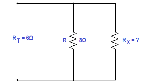
Figure 28 Example Parallel Circuit

Solution :

Rx = (RT .R) / (R – RT ) = (8×6)/(8+6) = 48/2 = 24 Ω

Don't Miss Our Updates
Be the first to get exclusive content straight to your email.
We promise not to spam you. You can unsubscribe at any time.
Invalid email address
You've successfully subscribed !

Continue Reading

Classification of Transformers
Wattmeter
Transformer Theory of Operation
Calculate Power in Parallel RL Circuit
Power in Balanced 3 Phase Loads
Low Voltage Protection (LVP) and Low Voltage Release (LVR)
Share This Article
Facebook Whatsapp Whatsapp LinkedIn Copy Link
Share
2 Comments
  • Herman Münchkrankenwißer says:
    June 30, 2022 at 8:45 pm

    Rt= 2k R= 1.2k
    Rx = (Rt.R)/(R-Rt)
    (2k .1.2k)/(1.2k – 2k)
    (2000 . 1200)/(1200 – 2000)
    2,400,000/ -800
    = -3k…………?

    So my resistor will actually be a superconductor?

    Reply
    • SM says:
      October 28, 2022 at 1:04 am

      Silly Herman. When you have two parallel resistors, you can’t have a total resistance that is greater than either of the two parallel resistors…..

      Reply

Leave a Reply Cancel reply

Your email address will not be published. Required fields are marked *

Stay Connected

128.3kFollowersLike
69.1kFollowersFollow
208kSubscribersSubscribe
38kFollowersFollow

Categories

Explore More

Single Line Diagram
Voltage and Current Phase Relationships in an Inductive Circuit
Capacitance
Calculate Power in Series RL Circuit
Three Phase Systems
Inductive Time Constant
Transformer Turns Ratio
AC Generator Voltage Regulators

Keep Learning

Developing a Sine-Wave Voltage of Motor

AC Generation

Unbalanced 3 Phase Loads

Unbalanced 3 Phase Loads

Parallel RLC Circuit

Impedance in RLC Circuits

4-Wire, Three-Phase Delta Wiring System

4-Wire, Three-Phase Delta Wiring System

Electrical Component Symbols

Electrical Diagrams and Schematics

Parallel Open Circuit Fault

Parallel Open Circuit Faults

Phase angle

AC Generation Analysis : Effective Values, Phase Angle and Frequency

relationship between resistance, reactance, and impedance

Impedance

Learn More

V1000 Family Programming Simulator Tool

VFD Simulator Download – Free Yaskawa V1000 Software

NEMA to IP Ratings

NEMA Enclosure Types Standards

Sox Nox Analyzer

Sox Nox Analyzer

foundation-fieldbus-vs-profibus

Comparison between Foundation Fieldbus and Profibus

Types of Interrupts Organization Blocks in Tia Portal

Types of Interrupt OB in Siemens Tia Portal

Instrumentation and Control Course

Free Instrumentation Course for Trainee Engineers

Stability in Frequency Domain

Mathematical Preliminaries

Instrumentation loop Diagram

Instrumentation Loop Diagrams

Follow US
All rights reserved. Reproduction in whole or in part without written permission is prohibited.
Welcome Back!

Sign in to your account

Username or Email Address
Password

Lost your password?