The level measurement is based on a hybrid technology: which consists of capacitance and GWR. The system is based on the GWR technology, whereas for interface applications this method is combined with a capacitive measurement.
The two technologies were chosen because of the performance of capacitance technology with emulsion layers and the GWR’s performance for precise overall level. The reference point R of the measurement is located at the process connection.
Hybrid Level Measurement
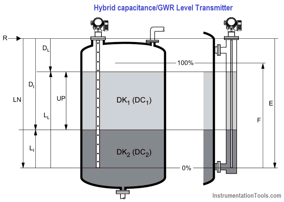
Figure – Hybrid capacitance/GWR measurement principle
Where,
R = reference point of measurement
E = empty calibration (= zero)
F = full calibration 1= span)
LN = probe length
UP thickness upper medium
DL = distace level complete
LL = level complete
D1 = distance interface (distance flange / DC2)
L1 = level interface (distance probe end / DC1)
The Measuring Range (example)
- Rod Probe ≤4 m/13 ft
- Rope Probe ≤10 m/33 ft
- Coaxial probe ≤6 m/20 ft
Interface with emulsion layer
If a clear interface layer exists, the hybrid system measures the overall level and the interface via the guided radar mode. In the background, the capacitive analysis always operates simultaneously and calculates the capacity value using the measured distances and the known capacitive conditions of the coaxial probe and derives the DC value of the oil layer from it.
This measured DC value is used, in turn, for the time‐of‐flight correction in the interface measurement through the oil layer which makes it possible to measure interfaces. Even in large DC value fluctuations of the upper hydrocarbon layer.
In traditional guided radar probes, the emulsion layer causes a loss of signal of the interface surface but keep the upper layer level (e.g. oil). The hybrid capacitance/GWR automatically switches to the capacitive mode and provide the lower level (water).
In presence of emulsion, the hybrid capacitance/GWR measures the upper layer level and the lower conductive layer below the emulsion. The overall emulsion layer cannot be known.
Limitations
- GWR and capacitance limitations also apply to the hybrid capacitance/GWR technology. In presence of emulsion, only the capacitance technology measures the presence of water.
- The DC of the upper medium should be known and constant.
- The DC of the upper medium may not be greater than 10.
- The DC difference between the upper medium and lower medium should be >10.
- The distance between the upper layer and the interface should minimum be 60 mm.
- Conductivity of the upper medium: <1 µS/cm
- Conductivity of the lower medium: >100 µS/cm
- Cannot measure a media which lead to fouling or heavy build up on the probe.
Selection
For interface measurement, ideally coax probes or rod probes in a chamber/cage/stilling well are used.
Coax probes are suited to liquids with viscosities of up to approximately 500cst. Coax probes can measure most liquefied gases, as of a dielectric constant of 1.4. Installation conditions, such as nozzles, vessel internal fittings etc. have no effect on the measurement when a coax probe is used. A coax probe offers maximum EMC safety when used in plastic vessels.
Rope probes may be used in a chamber/stilling well, if there is sufficient head room to install a rod probe. This can exclude the rope or end‐of‐probe weight touches the wall of the tube (diameter large enough, precisely vertical tube).
Design
The hybrid capacitance/GWR should have the right probe for the appropriate level range for the application.
Installation
Rod/rope probes can be mounted in a stilling well or chamber/cage. In this case, the distance of the rod/rope probe and internal diameter of the chamber/cage/stilling well should be between 40 mm and 100 mm. The distance from the end of rod/rode probe to the bottom of the vessel should minimum be 10 mm.
Coax probe can also be used and be mounted at an arbitrary distance from the wall of the vessel.
Within the measuring range, the rod/rope/coax probe should not get into contact with the chamber /cage/stilling well wall. If required, centre disks should be used. Centre disks should not be located in the measuring range.
For long rope/coax probe an additional weight or a spring should be considered.
For underground vessels rod/rope/coax probe should be designed with large nozzle diameters in order to avoid reflections at the nozzle wall.
For non‐metallic vessels coax probe is recommended.
For vessels with heat insulation, the electronic housing should be located outside the vessel insulation. This is to prevent the electronics from heating up as a result of heat radiation or convection.
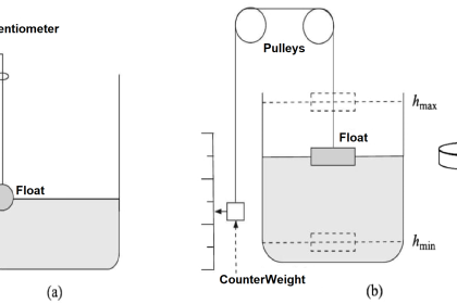
The insulation should not exceed the points labeled ‘max’ in the figure below.
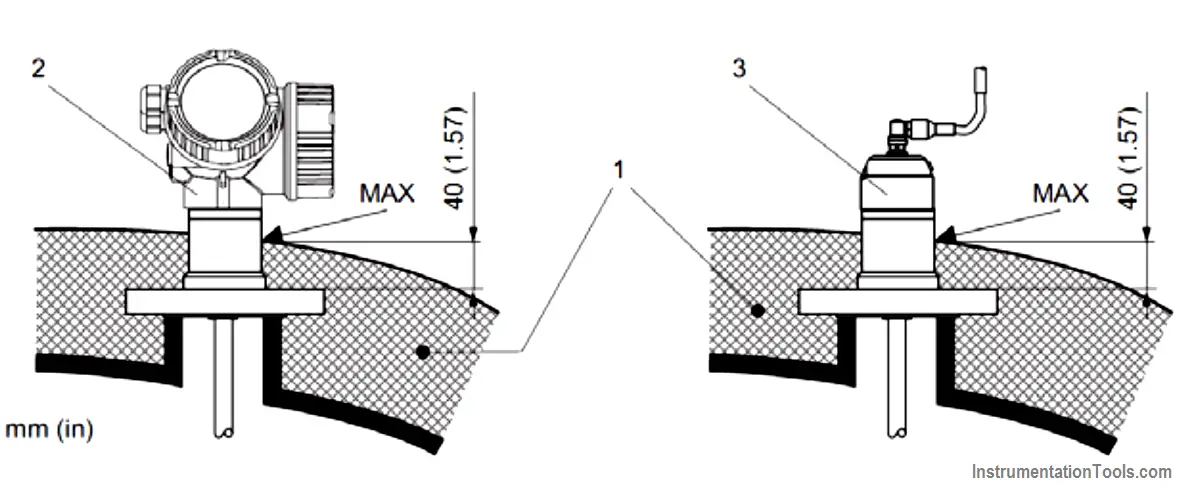
Figure – Hybrid capacitance or GWR level transmitter installation with heat insulation
Calibration and configuration for interface level measurement
Calibration is performed in the factory with complete assembly. In situ calibrations (low and high range) are only used for recording the linearity protocol. In case the calibration values are different from the factory ones they should be set as a customized parameterization.
The actual upper media DC value should be known.
- Wet calibration: The probe can be calibrated for its full range, i.e. lower interface level (0% level calibration) and high interface level (100% level). Other intermediate values can also be performed. Low interface level simulation aims to suppress the false echo (for GWR measurement) and provide 0% level value for the capacitance part. High interface level simulation aims to provide the maximum range value for both GWR measurement and capacitance part.
- Dry calibration: The level capacitance can be simulated by entering the low and high level values. Capacitance units will calculate automatically the capacitance variation image based in the factory calibration for ≥100 μS/cm.
Source : International Association of Oil & Gas Producers
Acknowledgements : IOGP Instrumentation and Automaton Standards Subcommittee (IASSC), BG Group, BP, Endress + Hauser, Emerson, Honeywell, Krohne, Petrobras, PETRONAS Carigali Sdn Bhd, Repsol, Siemens, Statoil, Total, Vega, Yokogawa.