Inst ToolsInst ToolsInst Tools
  • Ask
  • Courses
  • Videos
  • Q & A
    • Interview
      • Instrumentation
      • Electronics
      • Electrical
      • Practical Questions
    • MCQ
      • Instrumentation MCQ
      • Electrical MCQ
      • Electronics MCQ
      • Control Systems MCQ
      • Analog Electronics MCQ
      • Digital Electronics MCQ
      • Power Electronics MCQ
      • Microprocessor MCQ
      • Multiple Choice Questions
  • EE
    • Electronics
      • Electronics Q & A
      • Electronic Basics
      • Electronic Devices & Circuits
      • Electronics Animation
      • Digital Electronics
    • Electrical
      • Electrical Basics
      • Electrical Q & A
      • Power Electronics
      • Electrical Machines
      • Electrical Animation
      • Power Systems
      • Switchgear & Protection
      • Transmission & Distribution
  • Measure
    • Control Valves
    • Calibration
    • Temperature
    • Pressure
    • Flow
    • Level
    • Analyzers
    • Switches
    • Vibration
    • Solenoid Valve
  • Control
    • PLC Tutorials
    • Control Systems
    • Safety Instrumented System (SIS)
    • Communication
    • Fire & Gas System
  • More
    • Design
    • Tools
    • Animation
    • Basics
    • Formulas
    • Standards
    • TextBooks
    • Common
    • Software
    • Excel Tools
    • Erection & Commissioning
    • Process Fundamentals
    • Videos
    • Books
Search
All rights reserved. Reproduction in whole or in part without written permission is prohibited.
Reading: Falling Ball Viscometer Principle
Share
Notification Show More
Font ResizerAa
Inst ToolsInst Tools
Font ResizerAa
  • Courses
  • PLC Tutorials
  • Control Systems
Search
  • Ask
  • Courses
  • Videos
  • Q & A
    • Interview
    • MCQ
  • EE
    • Electronics
    • Electrical
  • Measure
    • Control Valves
    • Calibration
    • Temperature
    • Pressure
    • Flow
    • Level
    • Analyzers
    • Switches
    • Vibration
    • Solenoid Valve
  • Control
    • PLC Tutorials
    • Control Systems
    • Safety Instrumented System (SIS)
    • Communication
    • Fire & Gas System
  • More
    • Design
    • Tools
    • Animation
    • Basics
    • Formulas
    • Standards
    • TextBooks
    • Common
    • Software
    • Excel Tools
    • Erection & Commissioning
    • Process Fundamentals
    • Videos
    • Books
Follow US
All rights reserved. Reproduction in whole or in part without written permission is prohibited.
Inst Tools > Blog > Analyzers > Falling Ball Viscometer Principle

Falling Ball Viscometer Principle

Last updated: July 15, 2019 7:21 am
Editorial Staff
Analyzers
2 Comments
Share
4 Min Read
SHARE

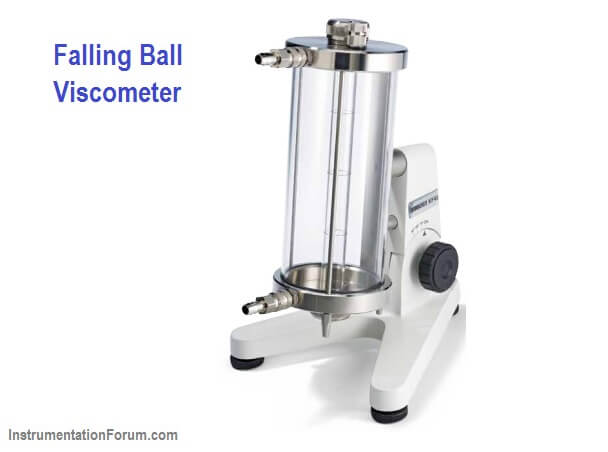
Falling Ball Viscometer uses the simple — but precise — Höppler principle to measure the viscosity of Newtonian liquids by measuring the time required for a ball to fall under gravity through a sample-filled tube.

The principle of the viscometer is to determine the falling time of a ball of known diameter and density through a close to vertical glass tube of known diameter and length, filled with the fluid to be tested.

The viscosity of the sample liquid is related to the time it takes for the ball to pass a distance between two specified lines on the cylindrical tube.

Turning the measurement tube results in returning of the ball and it is possible to re-measure the time over the same distance. The result is dynamic viscosity with the standard dimension.

Velocity of a ball which is falling through a liquid in a tube is dependent on the viscosity of the liquid. When the ball moves through the liquid, it is affected by the gravity, buoyancy and frictional forces: Gravity as downward force, buoyancy and friction as the upward forces.

Falling Ball Viscometer Principle

How It Works

The Falling Ball Viscometer is based on the measuring principle by Höppler for simple but precise dynamic viscosity measurement of transparent Newtonian fluids.

The basic concept is to measure the elapsed time required for the ball to fall under gravity through a sample-filled tube inclined at an angle*.

The tube is mounted on a pivot bearing which quickly allows rotation of the tube 180 degrees, thereby allowing a repeat test to run immediately.

Three measurements are taken and the average time it takes for the ball to fall is the result. A conversion formula turns the time reading into a final viscosity value.

Calibration Procedure

  • Fill the falling tube with studied liquid and put in the ball cautiously. Add more liquid till no air bubbles can be seen. Then close the falling tube by its cap.
  • Before starting the measurement, it is better to turn the falling tube up and down at least once in order to enhance temperature uniformity along the tube.
  • Turn the falling tube 180 degree. Start stop watch when the ball reaches to the first marks on the tube, and measure the time between the two marks. For better and more accurate results it is recommended to repeat the measurement 10 times at each temperature.
  • After changing the bath temperature, it’s highly recommended to wait at least 20 minutes to ensure temperature stability for the sample.
  • At the end of the experiment, empty the tube from the liquid and remove the ball from the tube very carefully. Clean the tube with suitable solvent and/or a brush.
  • Write down the density of liquid and ball respectively. Calculate the average time “t” for each temperature and calculate the viscosity using equation

Calibration

For calculating the viscometer constant, do all the above steps with a liquid which has a known viscosity such as distilled water but use the dynamic viscosity of distilled water in equation and calculate the viscometer constant, K.

Notes:

  • The liquid in the falling tube should be free of bubbles.
  • Generally the measurement for calibration is done at 20°C.
  • Measuring of the time starts when the lower edge of the ball touches the upper mark and ends when crosses the lower mark.
Don't Miss Our Updates
Be the first to get exclusive content straight to your email.
We promise not to spam you. You can unsubscribe at any time.
Invalid email address
You've successfully subscribed !
Flame Ionization Detector (FID) Principle
Basics of Chromatograph Operation
Gas chromatograph Working Animation
CEMS Principle, Types, Advantages, and Disadvantages
What is Gas Metering System?
Share This Article
Facebook Whatsapp Whatsapp LinkedIn Copy Link
Share
2 Comments
  • Jon Watson says:
    February 5, 2020 at 9:58 pm

    When first inverted the ball will start with zero velocity, its velocity increasing as it falls. At some point, if the ball is correctly sized for the anticipated viscosity, it will reach terminal viscosity before the first of the two marks and thus travel between them at constant velocity.
    However if the ball is too small it may reach terminal velocity only after having passed the first timing mark.

    This is an application of Stokes law. This allows the viscosity to be calculated from the elapsed time.
    https://en.wikipedia.org/wiki/Stokes%27_law
    However, this is not always a convenient way to approach falling ball measurements.
    Typical Hoppler viscometers are from Brookfield https://www.brookfieldengineering.com/products/viscometers/laboratory-viscometers/falling-ball-viscometer
    These methods produce the dynamic viscosity. In the hydrocarbon industry the kinematic viscosity is most commonly required which thus requires also the density.
    I’ve suggested that the Stokes law method allows a direct calculation of the viscosity and I have a query about the Hoeppler method.
    Does the method depend on establishing the terminal velocity or simply the time between two timing marks?
    If the latter then the conversion tables would, I suspect be based on the individual instrument and its original calibration. Can you comment on this?
    The only time I have come across the Stokes approach was in college and the Hoppler in various marine fuel testing applications.
    Such instruments are popular for their simplicity and speed of operation, important when sampling fuels as they are being bunkered.
    Of course, in most hydrocarbon measurements it is the kinematic viscosity that is required and that means also determining the density.

    Reply
  • Fatma El-Abyad says:
    September 8, 2020 at 6:08 pm

    what is the max range of viscosity this instrument can measure

    Reply

Leave a Reply Cancel reply

Your email address will not be published. Required fields are marked *

Stay Connected

128.3kFollowersLike
69.1kFollowersFollow
208kSubscribersSubscribe
38kFollowersFollow

Categories

Recent Comments

  • Kamli on Top Free PLC Software
  • Guifty Shimica on Top Non-PLC Certification Courses for Automation Professionals
  • Guifty Shimica on Top Non-PLC Certification Courses for Automation Professionals
  • MIHARITSOA Aina Sitraka on Top Non-PLC Certification Courses for Automation Professionals

Related Articles

Luft detector

Luft detector Principle

Metering components to measure flow of Natural gas

Is it Easy to Measure Natural Gas Flow and Volume?

dissolved-oxygen-probe-calibration-procedure

Dissolved oxygen probe calibration procedure

pH Analyzers Interview Questions Answers

pH Analyzer Interview Questions and Answers

Turbidity Sensor Calibration Procedure

Turbidity Sensor Calibration Procedure

Analytical Standards

gas chromatograph (GC)

Industrial Applications of Chromatographs

Infrared Flue Gas Analyser

What is Infrared Flue Gas Analyzer? – Working Principle

More Articles

Example Program Logic in Allen Bradley PLC

PLC Programming Examples on Industrial Automation

Wireless Electric Vehicle Charging

Wireless Electric Vehicle Charging

Jacket Added Seawater Pipe Spool

Seawater Pipeline Spools from day-1 leaks threaten Plant Shutdown

PLC Temperature Control using Pulse Width Modulation

PLC Temperature Control using Pulse Width Modulation (PWM)

automatic changeover switch explained

Automatic Transfer Switch – Electrical Circuit, Operation, Video

Integral Wind-Up Limitation

What is Integral Wind Up ?

Damaged Magnetic Flow Meter Flow Tube

None Could Repair Slightly Damaged Magnetic Flow Meter Flow Tube

Feed forward example

What is Feedforward Control ?

Follow US
All rights reserved. Reproduction in whole or in part without written permission is prohibited.
Welcome Back!

Sign in to your account

Username or Email Address
Password

Lost your password?