Inst ToolsInst ToolsInst Tools
  • Courses
  • Automation
    • PLC
    • Control System
    • Safety System
    • Communication
    • Fire & Gas System
  • Instrumentation
    • Design
    • Pressure
    • Temperature
    • Flow
    • Level
    • Vibration
    • Analyzer
    • Control Valve
    • Switch
    • Calibration
    • Erection & Commissioning
  • Interview
    • Instrumentation
    • Electrical
    • Electronics
    • Practical
  • Q&A
    • Instrumentation
    • Control System
    • Electrical
    • Electronics
    • Analog Electronics
    • Digital Electronics
    • Power Electronics
    • Microprocessor
  • Request
Search
  • Books
  • Software
  • Projects
  • Process
  • Tools
  • Basics
  • Formula
  • Power Plant
  • Root Cause Analysis
  • Electrical Basics
  • Animation
  • Standards
  • 4-20 mA Course
  • Siemens PLC Course
Reading: Ultrasonic Level Transmitter Principle, Limitations, Calibration and configuration
Share
Font ResizerAa
Inst ToolsInst Tools
Font ResizerAa
  • Courses
  • Design
  • PLC
  • Interview
  • Control System
Search
  • Courses
  • Automation
    • PLC
    • Control System
    • Safety System
    • Communication
    • Fire & Gas System
  • Instrumentation
    • Design
    • Pressure
    • Temperature
    • Flow
    • Level
    • Vibration
    • Analyzer
    • Control Valve
    • Switch
    • Calibration
    • Erection & Commissioning
  • Interview
    • Instrumentation
    • Electrical
    • Electronics
    • Practical
  • Q&A
    • Instrumentation
    • Control System
    • Electrical
    • Electronics
    • Analog Electronics
    • Digital Electronics
    • Power Electronics
    • Microprocessor
  • Request
Follow US
All rights reserved. Reproduction in whole or in part without written permission is prohibited.
Inst Tools > Blog > Calibration > Ultrasonic Level Transmitter Principle, Limitations, Calibration and configuration

Ultrasonic Level Transmitter Principle, Limitations, Calibration and configuration

Last updated: December 22, 2018 12:37 am
Editorial Staff
Calibration Level Measurement
2 Comments
Share
5 Min Read
SHARE

Measurement principle

Continuous non‐contacting ultrasonic level measurement is based on the time of flight principle.

An ultrasonic level instrument measures the time between sound energy transmitter from the sensor, to the surface of the measured material and the echo returning to the sensor.

As the speed of sound is known through the travel medium at a measured temperature, the distance to the surface is calculated. Level can be calculated from this distance measurement.

Echo Processing built in to the instrument can allow the instrument to determine the material level of liquids, solids or slurries even in narrow, obstructed or agitated vessels.

Limitations

Ultrasonic is seldom used in upstream hydrocarbon process stream for level measurement; it might be used in atmospheric utilities applications. In applications which are susceptible to vapour density variation, compensation reference pin should be used.

Maximum measurement distance should be checked against the technology (above 30 m the reflectivity may be reduced and might cause a measurement error/problem).

Ultrasonic sensors have, as physical limitation, a blocking distance (close to the sensor) where they cannot measure reliably, e.g. 0.25 metres.

Vessel pressure limitation should approximately be, e.g. 0.5 bar or less. Higher pressure may introduce uncertainty in the level measurement.

Vapour, vacuum or temperature gradients can influence the speed of sound and consequently can cause incorrect measurements.

Presence of foam or heavy turbulence on the surface of the measured material can cause unreliable measurement.

Selection

As ultrasonic is non‐contacting, even abrasive or aggressive materials can be measured. Vessel height and head room should be considered to select an instrument with suitable minimum and maximum range.

Design

Ultrasonic sensors should be made of a material suitable for the measured medium (e.g. PVDF or ETFE) Solid construction and a self‐cleaning action on the face of the sensor provide a reliable, low maintenance product.

Ultrasonic Level Transmitters Installation

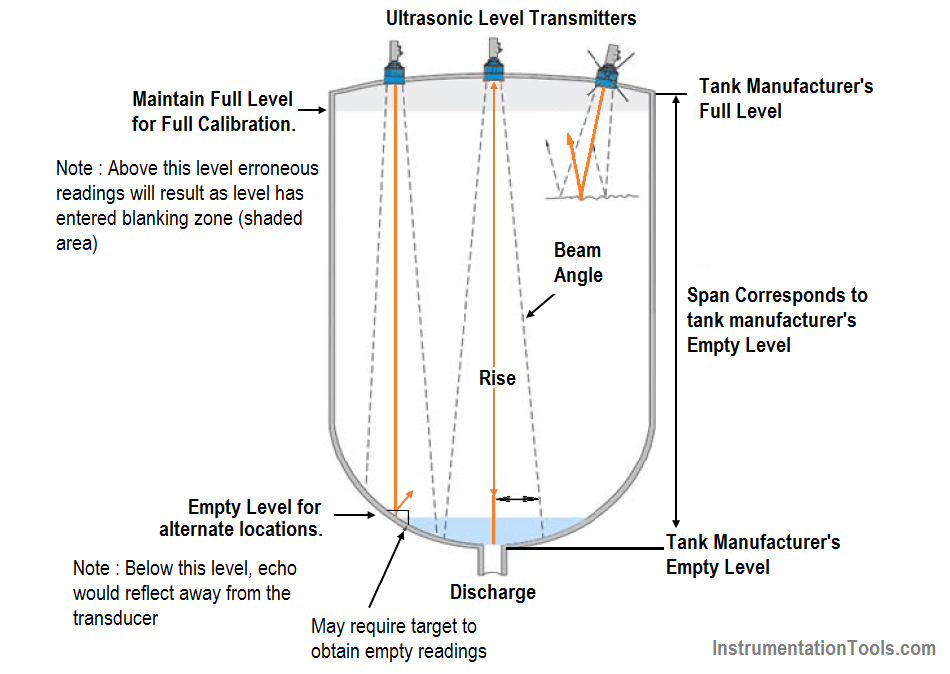
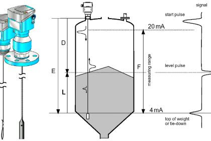
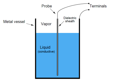
Figure – Ultrasonic Liquid Measurement Arrangement.

Use of a submergence shield on a sensor will allow an ultrasonic instrument to operate in potential flooding conditions reporting a full vessel to a control system or continuing to operate pumps to remove the flood condition.

Calibration and configuration

Ultrasonic Level Transmitters Calibration and configuration

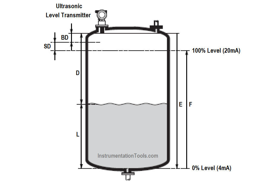
Figure – Ultrasonic Level Transmitter calibration

  • BD : Blocking Distance
  • SD : Safety Distance
  • E : Empty Calibration ( Zero Point )
  • F : Full Calibration ( Span )
  • D : Nozzle Diameter
  • L : Level

Performing an initial or ‘empty calibration’: In this principle, ‘enter’ the distance E from the sensor face to the minimum level (zero point). It is important to note that in vessels with parabolic roofs or bottoms, the zero point should not be more distant than the point at which the ultrasonic wave reflects from the tank bottom.

When possible, a flat target plate that is parallel to the sensor face and directly below the sensor mounting position should be added to the bottom of the vessel for best empty tank performance.

Once the empty distance has been set, the high calibration point or 100% full point can be set. This is done either by setting the distance from the sensor face to the 100% full level or by entering a span (level) from the 0% or low calibration point to the 100% full level.

During commissioning, ensure that the 100% full or high calibration point does not enter the ‘blocking distance’ or ‘blind zone’ of the respective sensor. This will vary from sensor to sensor. Blocking distances or blind zones can be extended to avoid false high level reflections caused by obstructions, but they can only be reduced to a certain distance due to the physical limitations of the sensor itself. The minimum level (distance E/zero point) should be configured. This zero point should be above any dished boiler heads or conical outflow located at the bottom of the tank/vessel.

The maximum level (distance F/full span) should be configured. This distance F should take into account both BD ‘blocking distance’ and SD ‘safety distances’.

Where BD represents a dead zone in which the wave cannot make any measurement and SD corresponds to a warning or an alarm zone.

Also Read : Ultrasonic Level Sensors Questions & Answers.

Source : International Association of Oil & Gas Producers

Acknowledgements : IOGP Instrumentation and Automaton Standards Subcommittee (IASSC), BG Group, BP, Endress + Hauser, Emerson, Honeywell, Krohne, Petrobras, PETRONAS Carigali Sdn Bhd, Repsol, Siemens, Statoil, Total, Vega, Yokogawa.

Don't Miss Our Updates
Be the first to get exclusive content straight to your email.
We promise not to spam you. You can unsubscribe at any time.
Invalid email address
You've successfully subscribed !

Continue Reading

Importance of Unit Measurement
Ultrasonic Level Transmitter Working Principle
Pressure Gauge Calibration Procedure
Why Measure Level
Hydrogen Sulfide Gas Detector Calibration Procedure
DeadWeight Tester Questions
Share This Article
Facebook Whatsapp Whatsapp LinkedIn Copy Link
Share
2 Comments
  • Shefeek says:
    July 26, 2019 at 1:27 pm

    The diameter of the Ultrasonic Sensor and the Diameter of vessel flang is also important,d=2D something like that

    Reply
  • Saddam hussain says:
    February 17, 2020 at 3:07 am

    This is very useful for us and it’s Very important for everyone…

    Reply

Leave a Reply Cancel reply

Your email address will not be published. Required fields are marked *

Stay Connected

128.3kFollowersLike
69.1kFollowersFollow
210kSubscribersSubscribe
38kFollowersFollow

Categories

Explore More

Contact Type Guided Wave Radar Level Transmitter Working Principle
Level Calculation with Remote Seals
Closed tank DP Level Transmitter with wet leg elevation zero direct mount Calibration
Instrumentation Engineer’s Calibration Mistakes
Multiphase Flow Meter Calibration Procedure
Different Types of Temperature Calibrators
Servo Tank Gauges Working Principle
pH Analyzer Calibration and Troubleshooting

Keep Learning

Boiler Three Element Controller Philosophy

Boiler Three Element Controller Philosophy

Level Gauges Questions and Answers

Level Gauges Objective Questions and Answers – Instrumentation

ORP-sensor-calibration

Oxidation-Reduction Potential (ORP) Sensor Calibration Procedure

Smart Transmitter Calibration Tutorial Part 3

Smart Transmitter Calibration Tutorial Part 3

Calibration Instruments

Basics of Calibration

Servo Level Transmitter Principle

Servo Level Transmitter Principle

How to Calibrate Load Cells

How to Calibrate Load Cells in Weighing Applications?

DP Level Measurement Problems

DP Level Measurement Problems

Learn More

PLC Program to Count and Pack Parts from conveyor

Count and Pack Objects from Conveyor using PLC Ladder Logic

Diaphragm Seal Transmitters Errors

Diaphragm Seal Transmitters Errors

Laser Diode Working Principle

Laser Diode Working Principle

Oxygen Measurement using Tunable Diode Laser System

Tunable Diode Laser Analyzer Working Principle

direct and reverse acting PID controller Tuning

Recognizing an Over-Tuned PID Controller by Phase Shift

Safety Instrumented Systems are different from Basic Process Control Systems

Safety Instrumented System Handbook – SIS Tutorials

Single Line Diagram

Single Line Diagram

Home Automation Project Ideas

Best Home Automation Project Ideas for Engineering Students

Menu

  • About
  • Privacy Policy
  • Copyright

Quick Links

  • Learn PLC
  • Helping Hand
  • Part Time Job

YouTube Subscribe

Follow US
All rights reserved. Reproduction in whole or in part without written permission is prohibited.
Welcome Back!

Sign in to your account

Username or Email Address
Password

Lost your password?