This is a PLC Program for the Water filling and discharging process using S7-1200 PLC.
Water filling and Discharging Process
Problem Description
In many industries or plants, there are lots of manual water filling systems are used for water storage.
In the manual system, there are so many disadvantages such as Accuracy, time delay problems, loss of liquids, and Time consuming.
And due to the manual system, we have to arrange an operator for machine operation. Water wastage occurs due to manual system
Here we are discussing a semi-automatic system.
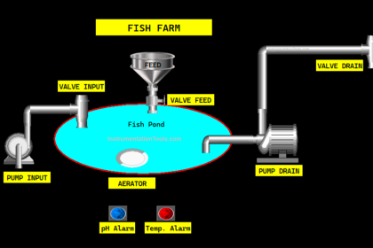
Diagram

PLC Solution
To solve this problem, we will use S7-1200 PLC for programming.
Here we use two sensors for level measurement, one is for High level and second is for low level.
We use feeding valve (MV1) for filling Cycle of the tank and discharge valve (MV2) for discharging cycle of the tank. Both will be controlled according to sensor logic.
So when the water level goes below low level then feeding valve will turned ON automatically and when water level reaches high and the it senses by high level sensor, then discharging process will be turned ON automatically.
When high level is detected then buzzer will turn ON for alarm purpose. Cycle will stop if user will press stop button from the control panel.
PLC Inputs and Outputs
Digital Inputs
- Start PB: I0.0
- Stop PB: I0.1
- TLB 1: I0.3
- TLB 2: I0.2
Digital Outputs
- Cycle ON: Q0.0
- Valve MV1 (Feed): Q0.1
- Valve MV2 (Discharge): Q0.2
- Agitator/Mixer M: Q0.3
- Buzzer: Q0.4
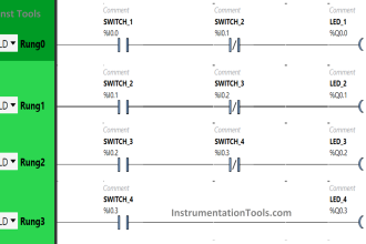
PLC Water Filling and Discharging Process

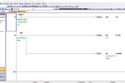
PLC Program Explanation
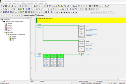
- For this application, we used S7-1200 PLC and TIA portal software for programming.
- In Network 1 we used latching circuit for cycle ON (Q0.0) output. It can be started by pressing START PB (I0.0) and stop by pressing STOP PB (I0.1).
- When cycle will be started then system will check level of the tank. If tank level is low then then feeding process will start and tank level is high then Discharge cycle will start.
- Here we have taken NO contact for both sensors in the program for simplicity. It can be done by relay logic in field or you can use such type of sensors.
- When tank will detect low level then TLB 2 (I0.2) will be activated and then feeding cycle will be ON. Here we have taken NC contact of TLB1 (I0.3) so when PLC will detect high level then it will stop Feeding cycle.
- When tank will detect high level then TLB 1 (I0.3) will be activated and discharging cycle will be ON. Here we have taken NC contact of TLB2 (I0.2) so when PLC will detect low level then it will stop discharge cycle cycle.
- Mixer M (Q0.3) should be ON during discharging cycle for mixing purpose.
- Here we also considered an alarm for high level to inform operator. When TLB 1(I0.3) will be detected then buzzer (Q0.4) will be activated.
- During all function, cycle should be ON.
Runtime Test Cases
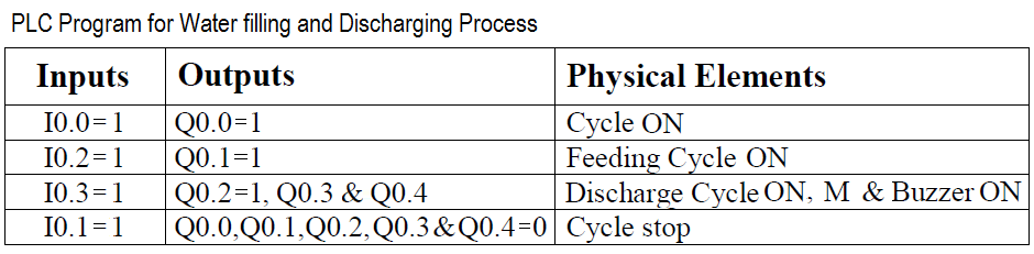
Note: The above PLC Logic provided for basic idea about application of PLC in Water filling and Discharging Process. The Logic is limited and not complete application.
Author: Bhavesh
If you liked this article, then please subscribe to our YouTube Channel for PLC and SCADA video tutorials.
You can also follow us on Facebook and Twitter to receive daily updates.
Read Next:


when TLB2 are in normal position then filling valve is operate and continue this will happen when level is below 0.1% to HI level.