Inst ToolsInst ToolsInst Tools
  • Courses
  • Automation
    • PLC
    • Control System
    • Safety System
    • Communication
    • Fire & Gas System
  • Instrumentation
    • Design
    • Pressure
    • Temperature
    • Flow
    • Level
    • Vibration
    • Analyzer
    • Control Valve
    • Switch
    • Calibration
    • Erection & Commissioning
  • Interview
    • Instrumentation
    • Electrical
    • Electronics
    • Practical
  • Q&A
    • Instrumentation
    • Control System
    • Electrical
    • Electronics
    • Analog Electronics
    • Digital Electronics
    • Power Electronics
    • Microprocessor
Search
  • Books
  • Software
  • Projects
  • Process
  • Tools
  • Basics
  • Formula
  • Power Plant
  • Root Cause Analysis
  • Electrical Basics
  • Animation
  • Standards
  • 4-20 mA Course
  • Siemens PLC Course
Reading: Liquid Flow Control Loop Controller Action
Share
Notification Show More
Font ResizerAa
Inst ToolsInst Tools
Font ResizerAa
  • Courses
  • Design
  • PLC
  • Interview
  • Control System
Search
  • Courses
  • Automation
    • PLC
    • Control System
    • Safety System
    • Communication
    • Fire & Gas System
  • Instrumentation
    • Design
    • Pressure
    • Temperature
    • Flow
    • Level
    • Vibration
    • Analyzer
    • Control Valve
    • Switch
    • Calibration
    • Erection & Commissioning
  • Interview
    • Instrumentation
    • Electrical
    • Electronics
    • Practical
  • Q&A
    • Instrumentation
    • Control System
    • Electrical
    • Electronics
    • Analog Electronics
    • Digital Electronics
    • Power Electronics
    • Microprocessor
Follow US
All rights reserved. Reproduction in whole or in part without written permission is prohibited.
Inst Tools > Blog > Control Systems > Liquid Flow Control Loop Controller Action

Liquid Flow Control Loop Controller Action

Last updated: September 7, 2019 7:00 am
Editorial Staff
Control Systems Practical Questions
2 Comments
Share
4 Min Read
SHARE

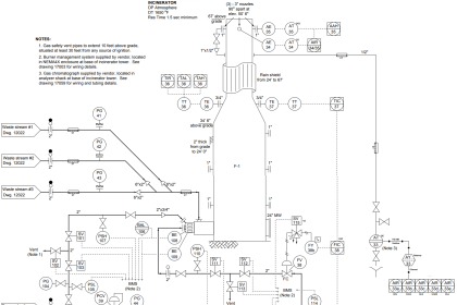
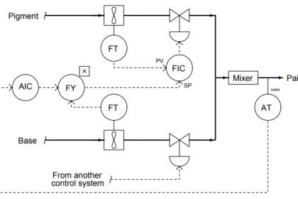
A liquid flow control loop consisting of a flow transmitter (FT) to sense liquid flow rate through the pipe and output an electronic signal corresponding to the flow.

Contents
Flow Control LoopAnswer :

A flow controller (FC) to sense the flow signal (from FT) and decide which way the control valve should move, a current-to-air (I/P) transducer (FY) to convert the controller’s electronic output signal into a variable air pressure, and an air-operated flow control valve (FV) to throttle the liquid flow:

Flow Control Loop

liquid flow control loop

The actions of each instrument are shown here:
  • FT: increasing liquid flow = increasing current signal
  • FC: increasing process variable (input) signal = decreasing output signal
  • FY: increasing current input signal = increasing pneumatic output signal
  • FV: increasing pneumatic signal = open more

Describe what will happen to all signals in this control loop with the controller in “automatic” mode (ready to compensate for any changes in flow rate by automatically moving the valve) if the pump were to suddenly spin faster and create more fluid pressure, causing an increase in flow rate.

Also describe what will happen to all signals in this control loop with the controller in “manual” mode (where the output signal remains set at whatever level the human operator sets it at) if the pump were to suddenly spin faster and create more fluid pressure, causing an increase in flow rate.

Extra Question :

Explain the practical benefit of having a “manual” mode in a process loop controller. When might we intentionally use manual mode in an operating process condition?

Answer :

In automatic mode:

Process flow rate (increase) → FT output signal (increase milliamps) → FC output signal (decrease milliamps) → FY output signal (decrease PSI) → FV position (moves further closed, pinching off liquid flow).

In manual mode:

Process flow rate (increase) → FT output signal (increase milliamps) → FC output signal (remains steady) → FY output signal (remains steady) → FV position (holds position).

The important part of this question is the difference in response between “automatic” and “manual” controller modes. In automatic control mode, the controller takes action to bring the process back to setpoint. In manual control mode, the controller just lets the process drift and takes no action to stop it.

At first, having a “manual” mode in a control system seems pointless. However, giving human operators the ability to manually override the otherwise automatic actions of a control system is important for start-up, shut-down, and handling emergency (unusual) conditions in a process system.

Manual mode is also a very important diagnostic tool for instrument technicians and operators alike. Being able to “turn off the brain” of an automatic control system and watch process response to manual changes in manipulated variable (final control element) signals gives technical personnel opportunity to test for unusual control valve behavior, process quirks, and other behaviors in a system that can lead to poor automatic control.

Share Your Answers via Comments
Don't Miss Our Updates
Be the first to get exclusive content straight to your email.
We promise not to spam you. You can unsubscribe at any time.
Invalid email address
You've successfully subscribed !

Continue Reading

Difference between Availability, Reliability & SIL
What is a Surge Protection Device? – Principle, Types, Advantages
Calculate the appropriate millivoltage values of a Thermocouple
Learn about PLC, DCS, RTU, SCADA, and PAC
Integral (Reset) Control Theory
How to Choose the Right Industrial Automation Solution?
Share This Article
Facebook Whatsapp Whatsapp LinkedIn Copy Link
Share
2 Comments
  • Mihir Ramkrishna says:
    March 27, 2019 at 10:46 am

    In Manual Mode especially if the PID block is implemented in the DCS and there are some interlocks implemented using the PV or MV of the PID block then that interlock or alarm is also bypassed. So the other advantage or should be we say the disadvantage would be the bypass of alarms or interlock in MAN mode.

    Reply
  • Karthik says:
    July 23, 2020 at 5:31 am

    When we want to control the flow of motor as our requirements flow rate that FT should be install after ( I mean flow for MOTOR – VALVE- FT ) the valve right.

    Then only we are sure that the flow rate is going as our requirements but we have installed FT in before that valve how we can sure the flow rate for after the valve. In this case, the valve has some issues or trouble valves given not proper output. please explain this. Thanking you

    Reply

Leave a Reply Cancel reply

Your email address will not be published. Required fields are marked *

Stay Connected

128.3kFollowersLike
69.1kFollowersFollow
208kSubscribersSubscribe
38kFollowersFollow

Categories

Explore More

Motor Trip Logic using PLC Programming
Basics of Alarms and Trips
Solenoid Valves Practical Problems
On/off Control Theory
Calculate the Voltage across Voltmeters of Thermocouple
Difference Between SCADA and HMI
Calculate PSV Lift Pressure
Pneumatic Relay Questions

Keep Learning

Calculate the Thermocouple Output millivolts

Calculate the Thermocouple Output millivolts

Industrial Automation and Control Systems (IACS)

Industrial Automation and Control Systems (IACS)

Pre-Engineering Design Documents

Industrial Automation Pre-Engineering Design Documents – Project & Process

Basics of Trips, Interlocks, Permissives & Sequences

Basics of Trips, Interlocks, Permissives & Sequences

Ziegler-Nichols closed-loop Formula

Tuning a Temperature Process Control Loop

Demo of a SCADA Software – Level Control System

Identify Process Variables in P&ID

Identify Process Variables in P&ID

How Twisted Wire Cables Eliminates Noise Voltage

Inductive Coupling Effects

Learn More

Electrical Machines Questions and Answers

Alternator Voltage Regulation Quiz

Electrical Switch Questions and Answers

Top 50 Electrical Switch Questions and Answers

Two-Conveyor PLC Control System

Basic Conveyor System for Product Handling in Omron PLC

pH and ORP eBook Download

pH and ORP Learning Handbook

Thermocouple Testing

Thermocouple Cold Junction Compensation

Single-element drum level control system

Single Element Drum Level Control System

Electronic Devices & Circuits Objective Questions

Electronic Devices & Circuits Quiz – Set 9

Components of PLC

Follow US
All rights reserved. Reproduction in whole or in part without written permission is prohibited.
Welcome Back!

Sign in to your account

Username or Email Address
Password

Lost your password?