In any process industry, level measurement is very important for safety and process purpose.
The level can be measured by two methods.
-
Direct method
-
Indirect method
Here we discuss the indirect method and which is using DP transmitter for level measurement.
A Differential pressure transmitter is a common and well-understood technology for liquid level measurement. If the tank is closed or pressurized, a DP measurement must be made to compensate for the vessel pressure.
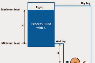
DP Transmitter Level Measurement for Closed Tank
In closed tank DP level measurement, LP leg is connected to the top of tank.
There are two methods in closed tank DP Level Measurement.
Dry leg method:
Dry leg method is used in normal close tank where vapor is not condensate and temperature of process is equal to atmospheric.
Wet leg method:
Wet leg method is used where vapor has a tendency to make the condensate and temperature of process is high or low from the atmospheric .
For DP Transmitter Configuration, we have to find out Zero Level & Span Level. Accordingly we have to configure Lower Range Value (LRV) and Upper Range Value (URV) using HART communicator.
DP Transmitter Level Measurement for Closed Tank – Dry Leg Method
Simply when LP side of the DP transmitter is filled with any gas/air then we call it as Dry Leg & we apply Dry Leg Method for calculations.

At zero level (LRV) = pressure acting on HP leg – Pressure acting on LP leg
=H2 x specific gravity – 0
= 200 x 0.9 – 0
= 180 mmwc
At 100 % level (URV) = pressure acting on HP leg – Pressure acting on LP leg
= (H2+H1) x specific gravity – 0
= (200 + 500) x 0.9 – 0
= 630 mmwc
Range = URV – LRV = 630 – 180 mmwc = 450 mmwc
So, we have to set Lower Range Value (LRV) = 180 mmwc and Upper Range Value (URV) = 630 mmwc in the DP Transmitter using HART communicator.
DP Transmitter Level Measurement for Closed Tank – Wet Leg Method
Simply when LP side of the DP transmitter is filled with liquid then we call it as Wet Leg & we apply Wet Leg Method for calculations.

Y = H1 +H2 = 500 + 200 = 700 mm
At zero level (LRV) = pressure acting on HP leg – Pressure acting on LP leg
= H2 x SG1 – Y x SG2
= 200 x 0.9 – 700 x 1.0
= 180 – 700
= – 520 mmwc
At 100 % level (URV) = pressure acting on HP leg – Pressure acting on LP leg
= (H2+H1) x SG1 – Y x SG2
= (200 + 500) x 0.9 – 700 x 1.0
= 630 – 700
= -70 mmwc
Range = URV – LRV = -70 – (-520) = 450 mmwc
So, we have to set Lower Range Value (LRV) = -520 mmwc and Upper Range Value (URV) = -70 mmwc in the DP Transmitter using HART communicator.
Author: Ashish Agrawal
Articles You May Like:
- Tank DP Level Transmitter
- Float level switch
- Paddle Wheel Level Switch
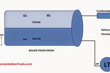
- Boiler Drum Level Transmitter
- DP Transmitter Auto Calibration


Dear Sir
I have question, why you neglect the LP side When you do a calculation on a dry leg mode? could you explaine that to me please?
Best regards
Ahmed
when we consider a dry leg, it means that LP side is subject to only Vapor / gas pressure, in the other hand the vapor/gas pressure is applied to both sides (LP and HP). so we don’t consider it (ie. the vapor/gas pressure) altogether.
LP is just as compensation for the internal tank pressure, so it does not contribute much during level measurement.
https://mycelectric.com
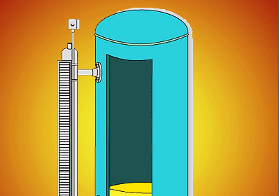
Horziontal close tank calibration procedure ( DP type transmitter)
capillery type LT
Very useful and explained in a way that can be understood easily.
Dear sir,
how to calculate single liquid LP & HP both side same spesifc graviti (0.838)
H1=90inch
h2=10inch
sg.f=0.838
sg.p=0.838
i have calculate and my answer had came LRV=-67.04 and URV=0 but once i hace feed same value but transmiter showing 167% like.
my transmiter is Husser+Endrees .
Pls let me know ASAP
As per the calculation
LRV = -74.88
URV = 0
In the diagram SG2 is 1.0 and while solving,u have taken the value SG2 as 1.2 ,
Kindly explain
HELLO,
ACCORDING TO MY KNOWLEDGE:
RANGE IS NOTHING BUT URV-LRV
SO,HERE IN THE ABOVE CASE i.e for DP Transmitter Level Measurement for Closed Tank – Wet Leg Method
To Cross Verify the Range: H1*SG1 = 500mm*0.9= 450mm;
Here in the above case at during verification Range:Range = URV – LRV = -210 – (-840) = 630 mmwc the LRV value instead of -660mmwc it is mentioned -840mmwc.I hope that is wrong and we cannot get the range that is to be attained.
you must be wrong.
Y = H1 +H2, what is Y, i have a confusion about it
there are two mistakes in this problem.
1. In diagram you specified a SG2 as 1.0 but in calculation you used as 1.2
2.range valve is URV-LRV= -210-(-660)= -210+660 =450mmwc.
so please verify before posting.. thnak you
Thanks for the notification. Now Updated. Next time we will do re-checks before posting.
In closed tank, wet leg, Y does not equal H1 + H2. Y is visibly longer. Either the diagram was not drawn well enough, and you intended the wet leg to be same as the 100% measurement, or your calcs are wrong, and the dimension for Y would be Y=H1+H2+(some other small height)
Why transmitter is always placed below the tank..?
Because pressure generate in bottom side
As you are measuring head pressure which via density and temperature wl be converted to level.
Dear sir
if we filled with glycol on both HP and LP tapping point on transmitter,what would be the LRV and URV, while calculating pressure acting on hp side?
Above scenario filled with liquid having SG=1 on LP side but on HP side having same SG as process fluid.this doubt arises because i have been working in a petrochemical industry where calculating the level of dp transmitter filled with glycol.
thanks and regards
LininRaj
email:linin991@gmail.com
Please explain boiler Level transmitter Reverse configuration i.e transmitter LP side connected with boiler bottom and HP side to top.
Hi
Should not the distance between the two taps be multiplied by the specific gravity of the liquid inside the tube to calculate the LRV? Why didn’t you use a specific gravity of 1 for height H2? Normally, the liquid inside both tubes is more or less the same, and the liquid inside the tank is different, unless we want to measure the water level.
for capillary type DP level transmitter, which formula will be used kindly suggest for better accuracy
What is the reason for using block and bleed valve as well as double block and bleed valve? Is there a governor for this issue? What are the disadvantages of using an isolation without bleeding?
Sir,
in wet leg method, while calculating the URV, the formula should be (H1 x Sg1)+(H2 x Sg2) – (Y x Sg2)
= H1Sg1 – H1 Sg2
What is zero elevation and suppression
Dpt type level transmitter connecting hp & lp single tube with tee fitting then what is purpose of that.