Inst ToolsInst ToolsInst Tools
  • Ask
  • Courses
  • Videos
  • Q & A
    • Interview
      • Instrumentation
      • Electronics
      • Electrical
      • Practical Questions
    • MCQ
      • Instrumentation MCQ
      • Electrical MCQ
      • Electronics MCQ
      • Control Systems MCQ
      • Analog Electronics MCQ
      • Digital Electronics MCQ
      • Power Electronics MCQ
      • Microprocessor MCQ
      • Multiple Choice Questions
  • EE
    • Electronics
      • Electronics Q & A
      • Electronic Basics
      • Electronic Devices & Circuits
      • Electronics Animation
      • Digital Electronics
    • Electrical
      • Electrical Basics
      • Electrical Q & A
      • Power Electronics
      • Electrical Machines
      • Electrical Animation
      • Power Systems
      • Switchgear & Protection
      • Transmission & Distribution
  • Measure
    • Control Valves
    • Calibration
    • Temperature
    • Pressure
    • Flow
    • Level
    • Analyzers
    • Switches
    • Vibration
    • Solenoid Valve
  • Control
    • PLC Tutorials
    • Control Systems
    • Safety Instrumented System (SIS)
    • Communication
    • Fire & Gas System
  • More
    • Design
    • Tools
    • Animation
    • Basics
    • Formulas
    • Standards
    • TextBooks
    • Common
    • Software
    • Excel Tools
    • Erection & Commissioning
    • Process Fundamentals
    • Videos
    • Books
Search
All rights reserved. Reproduction in whole or in part without written permission is prohibited.
Reading: Quantitative PID tuning procedures
Share
Notification Show More
Font ResizerAa
Inst ToolsInst Tools
Font ResizerAa
  • Courses
  • PLC Tutorials
  • Control Systems
Search
  • Ask
  • Courses
  • Videos
  • Q & A
    • Interview
    • MCQ
  • EE
    • Electronics
    • Electrical
  • Measure
    • Control Valves
    • Calibration
    • Temperature
    • Pressure
    • Flow
    • Level
    • Analyzers
    • Switches
    • Vibration
    • Solenoid Valve
  • Control
    • PLC Tutorials
    • Control Systems
    • Safety Instrumented System (SIS)
    • Communication
    • Fire & Gas System
  • More
    • Design
    • Tools
    • Animation
    • Basics
    • Formulas
    • Standards
    • TextBooks
    • Common
    • Software
    • Excel Tools
    • Erection & Commissioning
    • Process Fundamentals
    • Videos
    • Books
Follow US
All rights reserved. Reproduction in whole or in part without written permission is prohibited.
Inst Tools > Blog > Control Systems > Quantitative PID tuning procedures

Quantitative PID tuning procedures

Last updated: November 16, 2018 3:14 pm
Editorial Staff
Control Systems
No Comments
Share
4 Min Read
SHARE

A quantitative PID tuning procedure is a step-by-step approach leading directly to a set of numerical values to be used in a PID controller. These procedures may be split into two categories: open loop and closed loop. An “open loop” tuning procedure is implemented with the controller in manual mode: introducing a step-change to the controller output and then mathematically analyzing the results of the process variable response to calculate appropriate PID settings for the controller to use when placed into automatic mode.

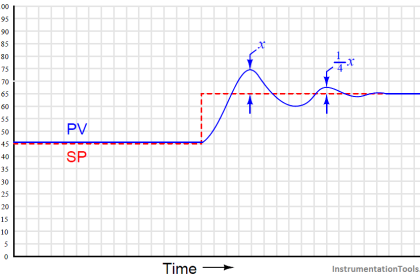
A “closed loop” tuning procedure is implemented with the controller in automatic mode: adjusting tuning parameters to achieve an easily-defined result, then using those PID parameter values and information from a graph of the process variable over time to calculate new PID parameters.

Quantitative PID tuning got its start with a paper published in the November 1942 Transactions of the American Society of Mechanical Engineers written by two engineers named Ziegler and Nichols. “Optimum Settings For Automatic Controllers” is a seminal paper, and deserves to be read by every serious student of process control theory. That Ziegler’s and Nichols’ recommendations for PID controller settings may still be found in modern references more than 60 years after publication is a testament to its impact in the field of industrial control.

Although dated in its terminology and references to pneumatic controller technology (some controllers mentioned as not even having adjustable proportional response, and others as having only discrete degrees of reset adjustment rather than continuously variable settings!), the PID algorithm described by its authors and the effects of P, I, and D adjustments on process control behavior are as valid today as they were then.

This article is devoted to a discussion of quantitative PID tuning procedures in general, and the “Ziegler-Nichols” methods in specific. It is the opinion of this author that the Ziegler-Nichols tuning methods are useful primarily as historical references, and indeed suffer from serious practical impediments. The most serious reservation I have with the Ziegler-Nichols methods (and in fact any algorithmic procedure for PID tuning) is that these methods tend to absolve the practitioner of responsibility for understanding the process they intend to tune.

Any time you provide people with step-by-step instructions to perform complex tasks, there will be a great many readers of those instructions tempted to mindlessly follow the instructions, even to their doom. PID tuning is one of these “complex tasks,” and there is significant likelihood for a person to do more harm than good if all they do is implement a step-by-step approach rather than understand what they are doing, why they are doing it, and what it means if the results do not meet with satisfaction. Please bear this in mind as you study any PID tuning procedure, Ziegler-Nichols or otherwise.

Types of Quantitative PID tuning procedures

  1. Ziegler-Nichols Closed-Loop Method
  2. Ziegler-Nichols Open-Loop Method
  3. Heuristic PID Tuning Method
Don't Miss Our Updates
Be the first to get exclusive content straight to your email.
We promise not to spam you. You can unsubscribe at any time.
Invalid email address
You've successfully subscribed !
Troubleshooting with Loop Calibrator
Design Process Graphics in Factory Talk View Studio with an Analog Input
Industry 4.0 Explained – Industrial Internet of Things
Types of Noise in Electronics
Design Logic Diagrams with Standard Formats for Process Control
Share This Article
Facebook Whatsapp Whatsapp LinkedIn Copy Link
Share
Leave a Comment

Leave a Reply Cancel reply

Your email address will not be published. Required fields are marked *

Stay Connected

128.3kFollowersLike
69.1kFollowersFollow
208kSubscribersSubscribe
38kFollowersFollow

Categories

Recent Comments

  • Kamli on Top Free PLC Software
  • Guifty Shimica on Top Non-PLC Certification Courses for Automation Professionals
  • Guifty Shimica on Top Non-PLC Certification Courses for Automation Professionals
  • MIHARITSOA Aina Sitraka on Top Non-PLC Certification Courses for Automation Professionals

Related Articles

Anti Surge Controller Theory

Anti Surge Controller Working Principle

Drum water level control

Closed Loop Control System : Boiler Water Level Control System

Ziegler-Nichols open-loop Tuning

Ziegler-Nichols Open-Loop Method

Voice Activated Industrial Automation

Voice Activated Industrial Automation Systems

Relay Internal Parts

Relay Operation, Types, Symbols & Characteristics

Basics of Trips, Interlocks, Permissives & Sequences

Basics of Trips, Interlocks, Permissives & Sequences

Centralized vs Decentralized Automation Systems

Centralized vs Decentralized Automation Systems

Industrial Automation Systems

Remote Functions in Industrial Control Systems (ICS)

More Articles

PLC Program to Energize & De-energize the Outputs based on Events

PLC Energize or De-energize the Outputs based on Events

How to Detect Speed of Conveyor in PLC

How to Detect Speed of Conveyor in PLC?

Foundation Fieldbus Interview Questions and Answers

Foundation Fieldbus Interview Questions and Answers

Differential Pressure versus Flow Rate

Orifice Flowmeter Rangeability

Wireless HART Transmitter

How to Commission WirelessHART Transmitter With Gateway

Servo Valve

Proportional Valve and Servo Valves

Inter Discipline Check (IDC)

What is Inter Discipline Check (IDC)?

Why Restriction Orifice is some distance from Blowdown valve

Why Restriction Orifice is some distance from Blowdown valve ?

Follow US
All rights reserved. Reproduction in whole or in part without written permission is prohibited.
Welcome Back!

Sign in to your account

Username or Email Address
Password

Lost your password?