Inst ToolsInst ToolsInst Tools
  • Ask
  • Courses
  • Videos
  • Q & A
    • Interview
      • Instrumentation
      • Electronics
      • Electrical
      • Practical Questions
    • MCQ
      • Instrumentation MCQ
      • Electrical MCQ
      • Electronics MCQ
      • Control Systems MCQ
      • Analog Electronics MCQ
      • Digital Electronics MCQ
      • Power Electronics MCQ
      • Microprocessor MCQ
      • Multiple Choice Questions
  • EE
    • Electronics
      • Electronics Q & A
      • Electronic Basics
      • Electronic Devices & Circuits
      • Electronics Animation
      • Digital Electronics
    • Electrical
      • Electrical Basics
      • Electrical Q & A
      • Power Electronics
      • Electrical Machines
      • Electrical Animation
      • Power Systems
      • Switchgear & Protection
      • Transmission & Distribution
  • Measure
    • Control Valves
    • Calibration
    • Temperature
    • Pressure
    • Flow
    • Level
    • Analyzers
    • Switches
    • Vibration
    • Solenoid Valve
  • Control
    • PLC Tutorials
    • Control Systems
    • Safety Instrumented System (SIS)
    • Communication
    • Fire & Gas System
  • More
    • Design
    • Tools
    • Animation
    • Basics
    • Formulas
    • Standards
    • TextBooks
    • Common
    • Software
    • Excel Tools
    • Erection & Commissioning
    • Process Fundamentals
    • Videos
    • Books
Search
All rights reserved. Reproduction in whole or in part without written permission is prohibited.
Reading: How to Test a Diode using Multimeter
Share
Notification Show More
Font ResizerAa
Inst ToolsInst Tools
Font ResizerAa
  • Courses
  • PLC Tutorials
  • Control Systems
Search
  • Ask
  • Courses
  • Videos
  • Q & A
    • Interview
    • MCQ
  • EE
    • Electronics
    • Electrical
  • Measure
    • Control Valves
    • Calibration
    • Temperature
    • Pressure
    • Flow
    • Level
    • Analyzers
    • Switches
    • Vibration
    • Solenoid Valve
  • Control
    • PLC Tutorials
    • Control Systems
    • Safety Instrumented System (SIS)
    • Communication
    • Fire & Gas System
  • More
    • Design
    • Tools
    • Animation
    • Basics
    • Formulas
    • Standards
    • TextBooks
    • Common
    • Software
    • Excel Tools
    • Erection & Commissioning
    • Process Fundamentals
    • Videos
    • Books
Follow US
All rights reserved. Reproduction in whole or in part without written permission is prohibited.
Inst Tools > Blog > Electronic Basics > How to Test a Diode using Multimeter

How to Test a Diode using Multimeter

Last updated: June 4, 2017 2:43 pm
Editorial Staff
Electronic Basics Electronic Devices & Circuits
5 Comments
Share
4 Min Read
SHARE

A multimeter can be used as a fast and simple way to check a diode out of the circuit. A good diode will show an extremely high resistance (ideally an open) with reverse bias and a very low resistance with forward bias. A defective open diode will show an extremely high resistance (or open) for both forward and reverse bias. A defective shorted or resistive diode will show zero or a low resistance for both forward and reverse bias. An open diode is the most common type of failure.

multimeter

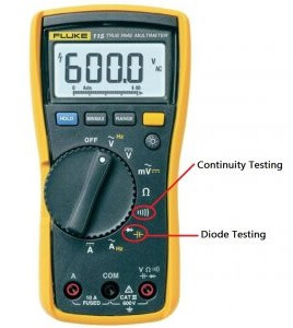
DMM Diode Test Position

Many digital multimeters (DMMs) have a diode test function that provides a convenient way to test a diode. A typical DMM has a small diode symbol to mark the position of the function switch. When set to diode test, the meter provides an internal voltage sufficient to forward-bias and reverse-bias a diode. This internal voltage may vary among different makes of DMM, but 2.5 V to 3.5 V is a typical range of values. The meter provides a voltage reading or other indication to show the condition of the diode under test.

Diode-testing-with-multimeter

When the Diode Is Working

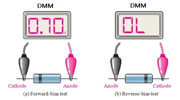
In Figure (a), the red (positive) lead of the meter is connected to the anode and the black (negative) lead is connected to the cathode to forwardbias the diode. If the diode is good, you will get a reading of between approximately 0.5 V and 0.9 V, with 0.7 V being typical for forward bias.

In Figure (b), the diode is turned around for reverse bias as shown. If the diode is working properly, you will typically get a reading of “OL”. Some DMMs may display the internal voltage for a reverse-bias condition.

When the Diode Is Defective

When a diode has failed open, you get an out-of-range “OL” indication for both the forward-bias and the reverse-bias conditions, as illustrated in Figure (c). If a diode is shorted, the meter reads 0 V in both forward- and reverse-bias tests, as indicated in part (d).

troubleshooting-a-diode

Checking a Diode with the OHMs Function

DMMs that do not have a diode test position can be used to check a diode by setting the function switch on an OHMs range. For a forward-bias check of a good diode, you will get a resistance reading that can vary depending on the meter’s internal battery. Many meters do not have sufficient voltage on the OHMs setting to fully forward-bias a diode and you may get a reading of from several hundred to several thousand ohms. For the reverse-bias check of a good diode, you will get an out-of-range indication such as “OL” on most DMMs because the reverse resistance is too high for the meter to measure.

Even though you may not get accurate forward- and reverse-resistance readings on a DMM, the relative readings indicate that a diode is functioning properly, and that is usually all you need to know. The out-of-range indication shows that the reverse resistance is extremely high, as you expect. The reading of a few hundred to a few thousand ohms for forward bias is relatively small compared to the reverse resistance, indicating that the diode is working properly. The actual resistance of a forward-biased diode is typically much less than 100 .

Don't Miss Our Updates
Be the first to get exclusive content straight to your email.
We promise not to spam you. You can unsubscribe at any time.
Invalid email address
You've successfully subscribed !
Transistor Collector Characteristic Curves
CRT Fluorescent Screen
Working of NPN Transistor
Short Circuit and Open Circuit
Series and Parallel Resistors
Share This Article
Facebook Whatsapp Whatsapp LinkedIn Copy Link
Share
5 Comments
  • Isaac Newton says:
    November 16, 2016 at 11:41 am

    Dear Bharadwaj ….
    Really good job ……….. appreciated.
    Earlier Printing option was there, but now I can not find it.
    Please allow the printing option.
    Thanks

    Reply
  • PRAVIN MAHESHKAR says:
    June 5, 2017 at 4:28 am

    Nice informative article …….

    Reply
  • Johnny says:
    June 5, 2017 at 6:34 am

    Your awesome, Very helpful. Thanks

    Reply
  • Girish Prasad Behera says:
    April 12, 2020 at 8:39 am

    thank sir for valuable information.

    Reply
  • Nzamurambaho Celestin says:
    November 5, 2020 at 1:12 pm

    Difference between short and open?

    Reply

Leave a Reply Cancel reply

Your email address will not be published. Required fields are marked *

Stay Connected

128.3kFollowersLike
69.1kFollowersFollow
208kSubscribersSubscribe
38kFollowersFollow

Categories

Recent Comments

  • Guifty Shimica on Top Non-PLC Certification Courses for Automation Professionals
  • Guifty Shimica on Top Non-PLC Certification Courses for Automation Professionals
  • MIHARITSOA Aina Sitraka on Top Non-PLC Certification Courses for Automation Professionals
  • Vaishnavi on Free Instrumentation Course for Trainee Engineers

Related Articles

resistor-color-coding-example

IEC labelling for Resistors Color Code

photo-diode

Photodiode Working Principle

Center Tapped Full Wave Rectifier Operation

Center Tapped Full Wave Rectifier Operation

Comparison of MOSFET and BJT

Comparison of MOSFET and BJT

Tank car bonding at siding

Electrical Static Grounding Techniques

light-emitting-diode-theory

Light Emitting Diode Operation

Derivation-of-Ohms-Law

Basics of Ohm’s Law

transistor-emitter-bias

Transistor Emitter Bias

More Articles

Radiochemical Questions and Answers

Gamma Camera Questions & Answers

Thermocouple Calculations

Thermocouple Calculations

Solid State Devices Objective Questions and Answers

Top 300 Solid State Devices Objective Questions and Answers

Compressor and Compressor valves Maintenance

Compressor & Compressor Valves Maintenance

Top 300 Electrical Circuits Objective Questions and Answers

Top 300 Electrical Circuits Objective Questions and Answers

Split-Range, Auto-Selector Ratio, And Cascade Systems

Split-Range, Auto-Selector, Ratio & Cascade Systems

Sealed Bellows Temperature Sensors

Bellows Pressure Sensors Working Principle Animation

Mixing Tank Relay Circuit

PLC Program for Mixing Tank

Follow US
All rights reserved. Reproduction in whole or in part without written permission is prohibited.
Welcome Back!

Sign in to your account

Username or Email Address
Password

Lost your password?