Inst ToolsInst ToolsInst Tools
  • Courses
  • Automation
    • PLC
    • Control System
    • Safety System
    • Communication
    • Fire & Gas System
  • Instrumentation
    • Design
    • Pressure
    • Temperature
    • Flow
    • Level
    • Vibration
    • Analyzer
    • Control Valve
    • Switch
    • Calibration
    • Standards
    • Basics
    • Formula
    • Erection & Commissioning
    • Process Fundamentals
    • Root Cause Analysis
  • Interview
    • Instrumentation
    • Electrical
    • Electronics
    • Practical
  • Q&A
    • Instrumentation
    • Control System
    • Electrical
    • Electronics
    • Analog Electronics
    • Digital Electronics
    • Power Electronics
    • Microprocessor
Search
  • Courses
  • PLC
  • Control Systems
All rights reserved. Reproduction in whole or in part without written permission is prohibited.
Reading: Open Tank Level Measurement using DP Transmitter
Share
Notification Show More
Font ResizerAa
Inst ToolsInst Tools
Font ResizerAa
  • Courses
  • PLC
  • Control Systems
Search
  • Courses
  • Automation
    • PLC
    • Control System
    • Safety System
    • Communication
    • Fire & Gas System
  • Instrumentation
    • Design
    • Pressure
    • Temperature
    • Flow
    • Level
    • Vibration
    • Analyzer
    • Control Valve
    • Switch
    • Calibration
    • Standards
    • Basics
    • Formula
    • Erection & Commissioning
    • Process Fundamentals
    • Root Cause Analysis
  • Interview
    • Instrumentation
    • Electrical
    • Electronics
    • Practical
  • Q&A
    • Instrumentation
    • Control System
    • Electrical
    • Electronics
    • Analog Electronics
    • Digital Electronics
    • Power Electronics
    • Microprocessor
Follow US
All rights reserved. Reproduction in whole or in part without written permission is prohibited.
Inst Tools > Blog > Level Measurement > Open Tank Level Measurement using DP Transmitter

Open Tank Level Measurement using DP Transmitter

Last updated: February 7, 2019 7:20 am
Editorial Staff
Level Measurement
3 Comments
Share
5 Min Read
SHARE

 Open Tank Level Measurement using DP Transmitter

Open Tank Level Measurement using DP Transmitter

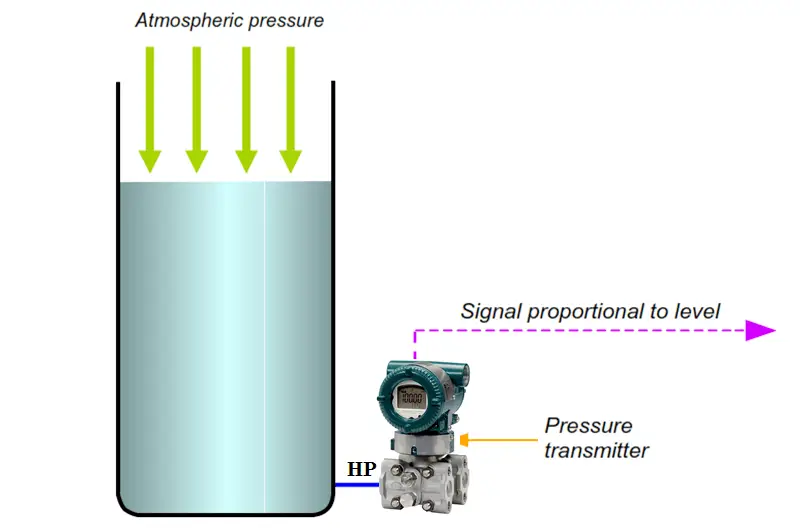
The figure above illustrates an application where the level value is inferred from a pressure measurement. When the level is at the same elevation point as the measuring instrument, atmospheric pressure is applied to both sides of the pressure transmitter and the measurement is at ‘zero’ reference level.

When the level in the tank increases, the force created by the hydrostatic head of the liquid is applied to the measurement side of the transmitter, resulting in an increase in the instrument output. The instrument response is caused by the head pressure is used to infer a level value.

The relationship between pressure and level is as mentioned earlier, P = ρ • h • g. Note that any changes in atmospheric pressure does not affect the measurement because the changes are applied to both sides of the pressure transmitter.

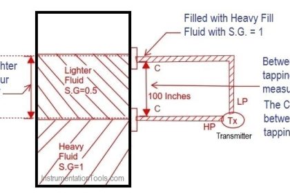
if we are using DP Transmitter then the HP side is connected to the tank tapping point and LP side is vent to atmosphere or we can use a pressure transmitter also.

The DP Transmitter calibration parameters will vary depending on installation & seal system also. Generally we can see three possibilities of installation of a transmitter.

They are :

  1. Transmitter installed Exactly at tapping point ( Ideal & preferred way of installation)
  2. Transmitter installed above tapping point ( Not preferable, Chance of bubble formation)
  3. Transmitter installed below tapping point (Error can be compensated effectively)

So we have to calibrate the transmitter depending on the type of installation in the field. The calibration formula will vary slightly depending on the installation.Every transmitter have two important parameters, they are Lower Range Value (LRV) & Upper Range Value (URV). We have to calculate the LRV & URV values based on type of installation. The below figures with formulas dictates the calculations. After calculating the values, configure the same parameters in the transmitter using HART communicator.

Here we are discussing two types of seal systems : with seal & without seal,

With Seal System : The impulse line is filled with special fluid like with glycerine, glycol etc

Without Seal System : Tank / Vessel fluid will be filled with the impulse lines

Configuration for Open Tank Level Measurement

Normal installation (Transmitter mounted leveled with min. level tap)

DP Transmitter Installed at HP tapping point

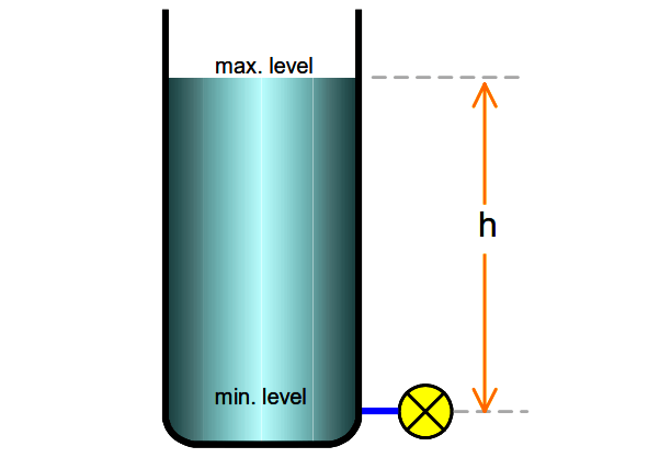
Regardless of whether with/without seal system;

Span = ρp • g • h ,or alternatively, Span = SGp • h

Elevated-Zero installation (Transmitter mounted above the tapping point)
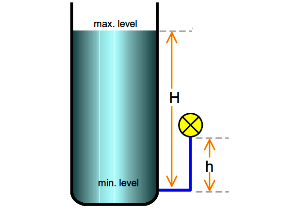
DP Transmitter Installed Above HP Tapping Point

With seal system;

Zero Elevation = − ( ρf • g • h) , or, = − (SGf • h)

Span = ρp • g • H , or, = SGp• H

Without seal system;

Note that this configuration is not advisable, because the transmitter tends to be unstable when the liquid level gets below the transmitter level – causing bubble trap, unless seal system is used.

Therefore, for calibration;

4mA (LRV) = Zero Elevation

20mA (URV) = Span + Zero Elevation

Suppressed-Zero installation (Transmitter mounted below the tapping point)
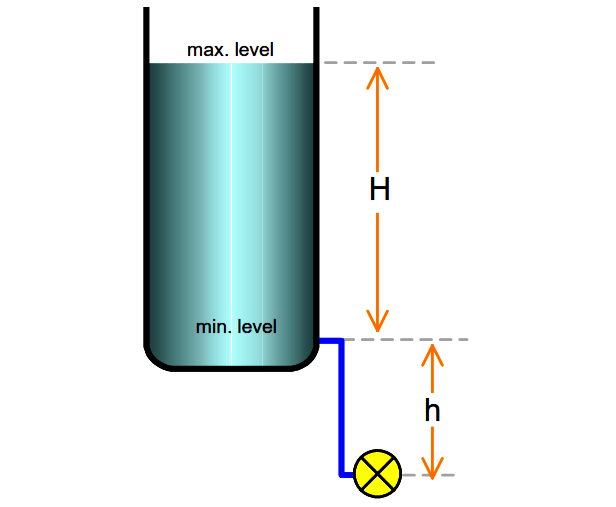
DP Transmitter Installed Below HP Tapping Point

With seal system;

Zero Suppression = ρf • g • h , or, = SGf • h

Span = ρp • g • H , or, = SGp • H

Without seal system;

(the transmitter leg is assumed to be filled with process fluid at all time)

Zero Suppression = ρf • g • h

Span = ρp • g • H , or, = SGp • H

Therefore, for calibration;

4mA (LRV) = Zero Suppression

20mA (URV) = Span + Zero Suppression

NOTE:

ρp = density of process liquid in the tank
SGp = std. gravity of process liquid.
ρf = density of fill-liquid in the tubing
SGf = std. gravity of fill liquid
H = Tank Height ( measured level)
h = transmitter installed height from the HP tapping point

Article Source : N. Asyiddin

Don't Miss Our Updates
Be the first to get exclusive content straight to your email.
We promise not to spam you. You can unsubscribe at any time.
Invalid email address
You've successfully subscribed !

Continue Reading

Ultrasonic Level Measurement
Level Measurement Terminology
Radar Level Transmitter in Briddle level Measurement
Point Level Detection Working Principle
Closed Tank Remote Seal Capillary type DP Transmitter
Cable Float Level Switch Working Principle
Share This Article
Facebook Whatsapp Whatsapp LinkedIn Copy Link
Share
3 Comments
  • johnny buch says:
    February 9, 2017 at 1:25 pm

    how far from the tank can you install the pressure transmitter ?

    Reply
  • kaifi azmi says:
    June 8, 2017 at 10:44 pm

    Plz.show a complete example with value

    Reply
  • Vishakh says:
    July 8, 2017 at 4:07 am

    the figure is confusing when comparing to the abbreviations in the questions

    Reply

Leave a Reply Cancel reply

Your email address will not be published. Required fields are marked *

Stay Connected

128.3kFollowersLike
69.1kFollowersFollow
208kSubscribersSubscribe
38kFollowersFollow

Categories

Explore More

Level Measurement with Dry leg and Installed Below Tapping Point
Radar and Ultrasonic Level Transmitter Practical Problems Troubleshooting
Drum Level Compensation and Range Calculation of DP Transmitter
Guided-Wave Radar Instruments Diagnostics
Bubbler Level Measurement Animation
Advantages & Disadvantages of Level Measurement Systems
Hydrostatic Tank Gauging (HTG)
Root Cause Analysis of Differential Pressure Level Transmitter

Keep Learning

Ultrasonic-Level-Transmitter-Animation

Ultrasonic Level Transmitter Animation

Types of Industrial Level Sensors

Types of Industrial Level Sensors

Level Gauge Interface Measurement

Level Gauge Interface & Temperature Problems

Capillary Remote Seal Leave Measurement

Siemens Pressure Transmitter with Remote Seals Calculations

Instruments Tapping Points

Instruments Tapping Points – Common versus Individual

Level Calculation with Remote Seals

Level Calculation with Remote Seals

Bubbler Liquid Level Transmitter Calculation

Bubbler Liquid Level Transmitter Calculation

Displacer Level Sensor

What is Displacer Level Sensor ?

Learn More

Guided Wave Radar Questions and Answers

Guided Wave Radar Questions and Answers

Digital Transducers Objective Questions

Digital Transducers Objective Questions

Convert Raw Counts to Engineering Units

Raw Counts to Engineering Units : Conversion Formula

compressor emergency shutdown system

Compressor Emergency Shutdown Root Cause Analysis

Metering pumps

Metering Pumps

Shunt-Wound DC Motor

Shunt-Wound Motor Operation

Sump Tank Level Transmitter

Problem with Sump Tank Level Transmitter

Instrument Panel Exhaust Fan Efficiency Improved

Instrument Panel Cooling Efficiency Enhancement

Follow US
All rights reserved. Reproduction in whole or in part without written permission is prohibited.
Welcome Back!

Sign in to your account

Username or Email Address
Password

Lost your password?