Inst ToolsInst ToolsInst Tools
  • Courses
  • Automation
    • PLC
    • Control System
    • Safety System
    • Communication
    • Fire & Gas System
  • Instrumentation
    • Design
    • Pressure
    • Temperature
    • Flow
    • Level
    • Vibration
    • Analyzer
    • Control Valve
    • Switch
    • Calibration
    • Erection & Commissioning
  • Interview
    • Instrumentation
    • Electrical
    • Electronics
    • Practical
  • Q&A
    • Instrumentation
    • Control System
    • Electrical
    • Electronics
    • Analog Electronics
    • Digital Electronics
    • Power Electronics
    • Microprocessor
  • Request
Search
  • Books
  • Software
  • Projects
  • Process
  • Tools
  • Basics
  • Formula
  • Power Plant
  • Root Cause Analysis
  • Electrical Basics
  • Animation
  • Standards
  • 4-20 mA Course
  • Siemens PLC Course
Reading: Temperature Sensor calibration procedure
Share
Font ResizerAa
Inst ToolsInst Tools
Font ResizerAa
  • Courses
  • Design
  • PLC
  • Interview
  • Control System
Search
  • Courses
  • Automation
    • PLC
    • Control System
    • Safety System
    • Communication
    • Fire & Gas System
  • Instrumentation
    • Design
    • Pressure
    • Temperature
    • Flow
    • Level
    • Vibration
    • Analyzer
    • Control Valve
    • Switch
    • Calibration
    • Erection & Commissioning
  • Interview
    • Instrumentation
    • Electrical
    • Electronics
    • Practical
  • Q&A
    • Instrumentation
    • Control System
    • Electrical
    • Electronics
    • Analog Electronics
    • Digital Electronics
    • Power Electronics
    • Microprocessor
  • Request
Follow US
All rights reserved. Reproduction in whole or in part without written permission is prohibited.
Inst Tools > Blog > Calibration > Temperature Sensor calibration procedure

Temperature Sensor calibration procedure

Last updated: September 15, 2016 9:43 pm
Editorial Staff
Calibration Temperature Measurement
1 Comment
Share
2 Min Read
SHARE

Most instrument manuals state there is no calibration of the temperature sensor, but the temperature sensor must be checked to determine its accuracy. This accuracy check is performed at least once per year and the accuracy check date/information is kept with the instrument.

If the accuracy check date/information is not included with the instrument or the last check was over a year, the temperature sensor accuracy needs to be checked at the beginning of the sampling event. If the instrument contains multiple temperature sensors, each sensor must be checked.

This procedure is not normally perform in the field. If the instrument is obtained from a rental company, the rental company should performed the calibration check and include with the instrument documentation that it was performed.

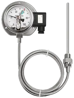
Temperature-gauge-calibration

Calibration Procedure:

1. Fill a container with water and adjust the water temperature to below the water body’s temperature to be measured. Use ice or warm water to adjust the temperature.

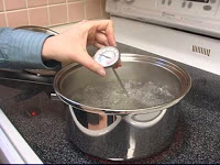
2. Place a thermometer that is traceable to the National Institute of Standards and Technology (NIST) and the instrument’s temperature sensor into the water. Wait for both temperature readings to stabilize.

3. Compare the two measurements. The instrument’s temperature sensor must agree with the reference thermometer measurement within the accuracy of the sensor (e.g.,±O.2°C). If the measurements do not agree, the instrument may not be working properly and the manufacturer needs to be consulted.Calibration-of-a-temperature-sensor

4. Adjust the water temperature to a temperature higher than the water body to be measured.

5. Compare the two measurements. The instrument’s temperature sensor must agree with the reference thermometer measurement within the accuracy of the sensor (e.g.,± 0.20 C). If the measurements do not agree, the instrument may not be working properly and the manufacturer needs to be consulted.
Don't Miss Our Updates
Be the first to get exclusive content straight to your email.
We promise not to spam you. You can unsubscribe at any time.
Invalid email address
You've successfully subscribed !

Continue Reading

RTD Calibration
Calibration Procedure of Weighing Balance and Common Mistakes
Hybrid Level Measurement Principle, Selection, Installation, Limitations and Calibration
Distributed Temperature Sensors (DTS) in Power Lines
Difference between Calibration and Ranging
Field Instrument Calibration Errors
Share This Article
Facebook Whatsapp Whatsapp LinkedIn Copy Link
Share
1 Comment
  • Mohan says:
    November 30, 2017 at 9:47 am

    What is 3 -Point Calibration especially for Thermcouples

    Reply

Leave a Reply Cancel reply

Your email address will not be published. Required fields are marked *

Stay Connected

128.3kFollowersLike
69.1kFollowersFollow
210kSubscribersSubscribe
38kFollowersFollow

Categories

Explore More

Shunt Calibration of a Strain Gauge Load Cell
Introduction to RTDs
Why it is important to note As-Found and As-Left data during Calibration?
RTD Sensor Connections
Burnout Function in Temperature Transmitter
H & B Gas Analyzer Principle and Calibration Procedure
Thermocouple Cold Junction Compensation
Pressure and Temperature Gauges

Keep Learning

Pressure Transmitter Calibration at the bench

Pressure Transmitter Calibration at the bench

calibrating-and-testing-rtd-sensors

RTD Calibration Procedure

non-contact pyrometers distance calculation

Non-contact Pyrometers Characteristics

How to Test a Pressure Gauge

How to Test a Pressure Gauge

Thermocouples Calibration Errors

Thermocouples Sources of Error

Magnehelic Gauge Calibration

Magnehelic Gauge Calibration

Thermocouples

Important Factors for Thermocouple Selection

RTD Connection Diagram

Difference Between 2 wire RTD, 3 wire RTD, and 4 wire RTD’s

Learn More

Lights with Adjustable Timers PLC Programming

Flip-Flop PLC Programming: Lights with Adjustable Timers

Innovative Segment Orifice

Stuck Segment Orifice Dimensions Calculations

Electric Stress Control in Cables, Joints and Terminations

Electric Stress Control in Cables, Joints, and Terminations

Power Electronics Objective Questions

PWM Inverters Multiple Choice Questions

Transmission and Distribution Interview Questions

Transmission and Distribution Interview Questions

On Off Valve Root Cause Analysis

Root Cause Analysis for FRP Line Damaged due to On-Off Valve

Analyzers Questions and Answers

Pulse Height Analyzer Questions & Answers

Digital Electronics Multiple Choice Questions

Memory Devices Objective Questions – Part 4

Menu

  • About
  • Privacy Policy
  • Copyright

Quick Links

  • Learn PLC
  • Helping Hand
  • Part Time Job

YouTube Subscribe

Follow US
All rights reserved. Reproduction in whole or in part without written permission is prohibited.
Welcome Back!

Sign in to your account

Username or Email Address
Password

Lost your password?