Inst ToolsInst ToolsInst Tools
  • Courses
  • Automation
    • PLC
    • Control System
    • Safety System
    • Communication
    • Fire & Gas System
  • Instrumentation
    • Design
    • Pressure
    • Temperature
    • Flow
    • Level
    • Vibration
    • Analyzer
    • Control Valve
    • Switch
    • Calibration
    • Erection & Commissioning
  • Interview
    • Instrumentation
    • Electrical
    • Electronics
    • Practical
  • Q&A
    • Instrumentation
    • Control System
    • Electrical
    • Electronics
    • Analog Electronics
    • Digital Electronics
    • Power Electronics
    • Microprocessor
  • Request
Search
  • Books
  • Software
  • Projects
  • Process
  • Tools
  • Basics
  • Formula
  • Power Plant
  • Root Cause Analysis
  • Electrical Basics
  • Animation
  • Standards
  • 4-20 mA Course
  • Siemens PLC Course
Reading: 2-wire Transmitters Current Loops
Share
Font ResizerAa
Inst ToolsInst Tools
Font ResizerAa
  • Courses
  • Design
  • PLC
  • Interview
  • Control System
Search
  • Courses
  • Automation
    • PLC
    • Control System
    • Safety System
    • Communication
    • Fire & Gas System
  • Instrumentation
    • Design
    • Pressure
    • Temperature
    • Flow
    • Level
    • Vibration
    • Analyzer
    • Control Valve
    • Switch
    • Calibration
    • Erection & Commissioning
  • Interview
    • Instrumentation
    • Electrical
    • Electronics
    • Practical
  • Q&A
    • Instrumentation
    • Control System
    • Electrical
    • Electronics
    • Analog Electronics
    • Digital Electronics
    • Power Electronics
    • Microprocessor
  • Request
Follow US
All rights reserved. Reproduction in whole or in part without written permission is prohibited.
Inst Tools > Blog > Common > 2-wire Transmitters Current Loops

2-wire Transmitters Current Loops

Last updated: December 11, 2018 12:31 pm
Editorial Staff
Common Control Systems
1 Comment
Share
5 Min Read
SHARE

2-wire (“loop-powered”) transmitter current loops

It is possible to convey electrical power and communicate analog information over the same two wires using 4 to 20 milliamps DC, if we design the transmitter to be loop-powered. A loop powered transmitter connects to a process controller with only two wires, which is why loop-powered transmitters are synonymously known as 2-wire transmitters:

Note :

  • Here in this article, we are assuming a simple microcontrollers based controllers is connected with a 2 wire transmitters.
  • For a PLC/DCS systems, the standard resistor & Analog to Digital Converters (ADC) are found in Analog Input (AI) Cards.

2 wire transmitter current loops

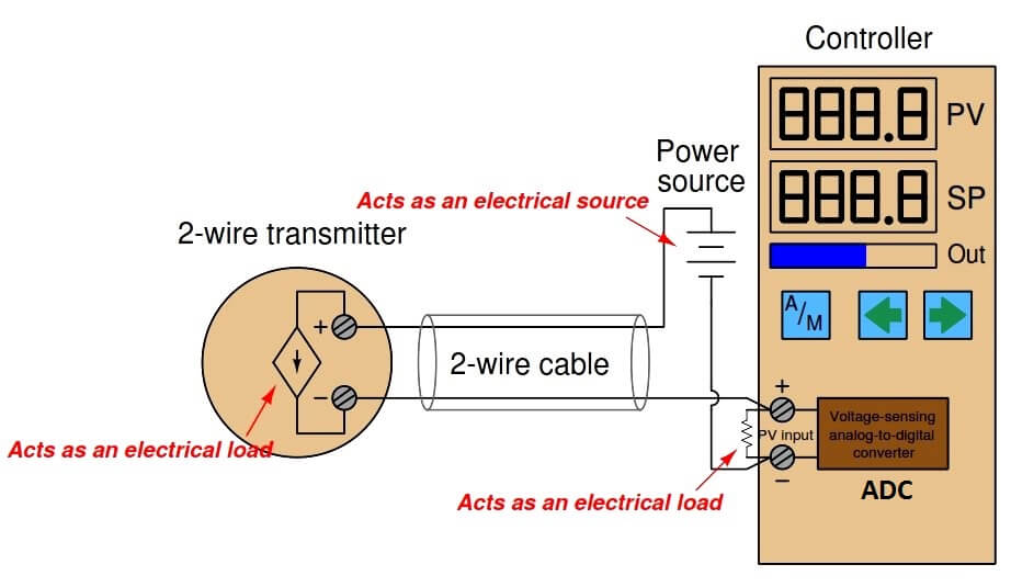
Here, the transmitter is not really a current source in the sense that a 4-wire transmitter is. Instead, a 2-wire transmitter’s circuitry is designed to act as a current regulator, limiting current in the series loop to a value representing the process measurement, while relying on a remote source of power to motivate the electric current. Please note the direction of the arrow in the transmitter’s dependent current source symbol, and how it relates to the voltage polarity marks. Refer back to the illustration of a 4-wire transmitter circuit for comparison. The current “source” in this loop powered transmitter actually behaves as an electrical load , while the current source in the 4-wire transmitter functioned as a true electrical source.

A loop-powered transmitter gets its operating power from the minimum terminal voltage and current available at its two terminals. With the typical source voltage being 24 volts DC, and the maximum voltage dropped across the controller’s 250 ohm resistor being 5 volts DC, the transmitter should always have at least 19 volts available at its terminals. Given the lower end of the 4-20 mA signal range, the transmitter should always have at least 4 mA of current to function on. Thus, the transmitter will always have a certain minimum amount of electrical power available on which to operate, while regulating current to signal the process measurement to the receiving instrument.

Internally, the electronic hardware of a 2-wire transmitter circuitry resembles the following (simplified) diagram. Note that everything shown within the shaded rectangle is represented by the “2-wire transmitter” circle in the previous diagram:

2-wire transmitter circuit

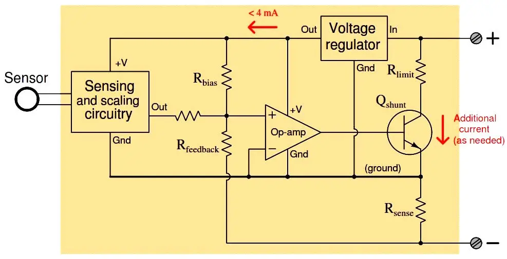
Fig : 2-wire transmitter circuit

All sensing, scaling, and output conditioning circuitry inside the transmitter must be designed to operate on less than 4 mA of DC current, and at a modest terminal voltage. In order to create loop currents exceeding 4 mA – as the transmitter must do in order to span the entire 4 to 20 milliamp signal range – the transmitter circuitry uses a transistor to shunt (bypass) extra current from one terminal to the other as needed to make the total current indicative of the process measurement.

For example, if the transmitter’s internal operating current is only 3.8 mA, and it must regulate loop current at a value of 16 mA to represent a condition of 75% process measurement, the shunt transistor will be driven by the opamp to bypass exactly 12.2 mA of current (because 3.8 mA + 12.2 mA = 16.0 mA). The very low amount of electrical power available at a 2-wire transmitter’s terminals limits its functionality.

Early current-based industrial transmitters were not capable of operating on such low levels of electrical power, and so used a different current signal standard: 10 to 50 milliamps DC. Loop power supplies for these transmitters ranged upwards of 90 volts to provide enough power for the transmitter. Safety concerns made the 10-50 mA standard unsuitable for some industrial installations, and modern microelectronic circuitry with its reduced power consumption made the 4-20 mA standard practical for nearly all types of process transmitters.

Credits : by Tony R. Kuphaldt – Creative Commons Attribution 4.0 License

Don't Miss Our Updates
Be the first to get exclusive content straight to your email.
We promise not to spam you. You can unsubscribe at any time.
Invalid email address
You've successfully subscribed !

Continue Reading

Distributed Control System Objective Questions
Voice Activated Industrial Automation Systems
The Most Significant Developments in Satellite Technology
Understanding the Chiller Maintenance – HVAC Tutorials
The Role of Test Automation in a Single Sprint – 5 Steps to Follow
Key Facts About RS485 Industrial Network
Share This Article
Facebook Whatsapp Whatsapp LinkedIn Copy Link
Share
1 Comment
  • Abel Tamang says:
    April 16, 2023 at 5:58 am

    Excellent tutorial. Thank you so much.

    Reply

Leave a Reply Cancel reply

Your email address will not be published. Required fields are marked *

Stay Connected

128.3kFollowersLike
69.1kFollowersFollow
210kSubscribersSubscribe
38kFollowersFollow

Categories

Explore More

Proximity Sensor
What is Anti Surge System?
Foundation Fieldbus Split Range Valves
Embarking on a Homebrew CNC Project: A Journey of Creativity
Types of Sensors used in the Dairy Industry
ESD System Insights: Signals for Emergency Valve Shutdown Explained
What is Electromagnetic Noise Interference?
What is a Annunciator Panel?

Keep Learning

Electrical Circuit Label Schematic

Label the Electrical Circuit Schematic

cascade temperature controller

How to Analyze a Cascade Control Loop?

Address Resolution Protocol (ARP)

What is the Address Resolution Protocol? – Types of ARP

Tips to Maintain & Extend the Life of CNC Tools

Tips for Maintaining and Extending the Life of Your CNC Tools

Data Preparation for AI

Data Preparation for AI: For Successful Machine Learning

Oil Burners

What are Oil Burners? Types, Advantages, Applications

Electrical Drives Animation

Electrical Drives – Modes, Types, Speed Control Applications

Top 10 Podcasts about Electronics

Top 10 Podcasts about Electronics

Learn More

Material Certificate versus Positive Material Identification (PMI)

Material Certificate versus Positive Material Identification (PMI)

Choke Input Filter Operation

Choke Input Filter Operation

Smart Valve Monitoring

SIS Instruments and Valves Inline Testing – Safety Instrumented System

Turbine to Gearbox Alignment Drifts Caused Pump Transfers Problems

RCA Related to Trip Throttle Valve (TTV)

Steam flow to the heat exchanger

Analytical Control System of Heat Exchanger Questions

Backwashing Precoat Filters

Backwashing Precoat Filters

Sensors and Transducers Objective Questions

Transducers Objective Questions

Quiz on Manual Motor Starters

100 Quiz Questions on Manual Motor Starters

Menu

  • About
  • Privacy Policy
  • Copyright

Quick Links

  • Learn PLC
  • Helping Hand
  • Part Time Job

YouTube Subscribe

Follow US
All rights reserved. Reproduction in whole or in part without written permission is prohibited.
Welcome Back!

Sign in to your account

Username or Email Address
Password

Lost your password?