Inst ToolsInst ToolsInst Tools
  • Courses
  • Automation
    • PLC
    • Control System
    • Safety System
    • Communication
    • Fire & Gas System
  • Instrumentation
    • Design
    • Pressure
    • Temperature
    • Flow
    • Level
    • Vibration
    • Analyzer
    • Control Valve
    • Switch
    • Calibration
    • Erection & Commissioning
  • Interview
    • Instrumentation
    • Electrical
    • Electronics
    • Practical
  • Q&A
    • Instrumentation
    • Control System
    • Electrical
    • Electronics
    • Analog Electronics
    • Digital Electronics
    • Power Electronics
    • Microprocessor
  • Request
Search
  • Books
  • Software
  • Projects
  • Process
  • Tools
  • Basics
  • Formula
  • Power Plant
  • Root Cause Analysis
  • Electrical Basics
  • Animation
  • Standards
  • 4-20 mA Course
  • Siemens PLC Course
Reading: PLC Data Comparison Instructions
Share
Font ResizerAa
Inst ToolsInst Tools
Font ResizerAa
  • Courses
  • Design
  • PLC
  • Interview
  • Control System
Search
  • Courses
  • Automation
    • PLC
    • Control System
    • Safety System
    • Communication
    • Fire & Gas System
  • Instrumentation
    • Design
    • Pressure
    • Temperature
    • Flow
    • Level
    • Vibration
    • Analyzer
    • Control Valve
    • Switch
    • Calibration
    • Erection & Commissioning
  • Interview
    • Instrumentation
    • Electrical
    • Electronics
    • Practical
  • Q&A
    • Instrumentation
    • Control System
    • Electrical
    • Electronics
    • Analog Electronics
    • Digital Electronics
    • Power Electronics
    • Microprocessor
  • Request
Follow US
All rights reserved. Reproduction in whole or in part without written permission is prohibited.
Inst Tools > Blog > PLC Tutorials > PLC Data Comparison Instructions

PLC Data Comparison Instructions

Last updated: March 4, 2021 4:43 pm
Editorial Staff
PLC Tutorials
No Comments
Share
4 Min Read
SHARE

As we have seen with counter and timers, some PLC instructions generate digital values other than simple Boolean (on/off) signals.

Counters have current value (CV) registers and timers have elapsed time (ET) registers, both of which are typically integer number values.

Many other PLC instructions are designed to receive and manipulate non-Boolean values such as these to perform useful control functions.

The IEC 61131-3 standard specifies a variety of data comparison instructions for comparing two non-Boolean values, and generating Boolean outputs.

PLC Data Comparison Instructions

The basic comparative operations of “less than” (<), “greater than” (>), “less than or equal to” (≤), “greater than or equal to” (≥), “equal to” (=), and “not equal to” (6=) may be found as a series of “box” instructions in the IEC standard:

PLC Data comparison instructions

The Q output for each instruction “box” activates whenever the evaluated comparison function is “true” and the enable input (EN) is active.

If the enable input remains active but the comparison function is false, the Q output de-activates. If the enable input de-de-activates, the Q output retains its last state.

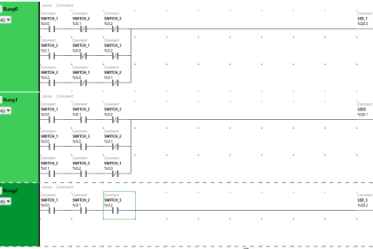
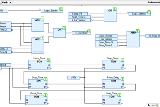
A practical application for a comparative function is something called alternating motor control, where the run-times of two redundant electric motors are monitored, with the PLC determining which motor to turn on next based on which motor has run the least:

PLC Push Button Wiring
PLC on-delay timers logic

.In this program, two retentive on-delay timers keep track of each electric motor’s total run time, storing the run time values in two registers in the PLC’s memory:

Motor A runtime and Motor B runtime. These two integer values are input to the “greater than” instruction box for comparison.

If motor A has run longer than motor B, motor B will be the one enabled to start up next time the “start” switch is pressed.

If motor A has run less time or the same amount of time as motor B (the scenario shown by the blue-highlighted status indications), motor A will be the one enabled to start.

The two series-connected virtual contacts OUT motor A and OUT motor B ensure the comparison between motor run times is not made until both motors are stopped.

If the comparison were continually made, a situation might arise where both motors would start if someone happened to press the Start pushbutton with one motor is already running.

Credits : by Tony R. Kuphaldt – Creative Commons Attribution 4.0 License

PLC Tutorials :

  • What is Programmable Logic Controller  ?
  • What is Ladder Diagram Programming ?
  • History of Programmable Logic Controllers
  • Mis-conceptions of PLC Ladder Logic
  • Contacts and coils in PLC
  • Digital Input and Output Modules
  • Analog I/O and Network I/O
  • PLC Input/Output Modules
  • Memory Mapping in PLC
  • Analog Input Scaling
  • PLC Example with Switches
  • Counter Instructions
  • Timer Instructions
  • Math instructions
  • Data Instructions
  • Ladder Logic Questions

If you liked this article, then please subscribe to our YouTube Channel for PLC and SCADA video tutorials.

You can also follow us on Facebook and Twitter to receive daily updates.

Don't Miss Our Updates
Be the first to get exclusive content straight to your email.
We promise not to spam you. You can unsubscribe at any time.
Invalid email address
You've successfully subscribed !

Continue Reading

How to Use the Shift and Rotate Instructions in PLC?
Process Interlocks and Trips
Mail Box Automation: Programming with Schneider PLC
How to Create Templates in FactoryTalk View Studio?
SCADA Hardware and Software
Features of Scada Which are Must in an IoT System
Share This Article
Facebook Whatsapp Whatsapp LinkedIn Copy Link
Share
Leave a Comment

Leave a Reply Cancel reply

Your email address will not be published. Required fields are marked *

Stay Connected

128.3kFollowersLike
69.1kFollowersFollow
210kSubscribersSubscribe
38kFollowersFollow

Categories

Explore More

Difference between Power Cables and Signal Cables
Remote Factory Acceptance Test
Function Blocks in PLC (FBs) – What You Need To Know?
Anti-static Wrist Straps in Industrial Automation
PLC Program for Controlling Sequence of Conveyors with Interlock
Peripheral Inputs and Outputs in Siemens PLC
What is Interposing Relay in a PLC System ?
SCADA Engineer Job Responsibilities and Skills

Keep Learning

How to use Scale and Normalize Instructions in PLC

Scale and Normalize Instructions in PLC

PLC Programming Sequence Logic

PLC Programming to Control Lights in a Sequence

Distributed IO for Siemens PLC

How to Configure Distributed IO in a PLC Project?

How a PLC communicates with Transmitters

How PLC Reads the Data from Field Transmitters

One-Shot Rising and Falling Edge Instructions in Rockwell PLC

One-Shot Rising and Falling Edge Instructions in Rockwell PLC

Allen Bradley PLC Example with Sub routines

How to use Sub Routines with Allen Bradley PLC

Siemens PLC motor direction control example

Siemens TIA Portal: Motor Forward Reverse PLC Logic

DC Circuit

Main differences between Sinking and Sourcing Circuits

Learn More

Safety Instrumented System Engineer Interview Questions

Safety Instrumented Systems Online Exam

PID Block in RSLogix 500

PID Block in RSLogix 500

Transformer Efficiency and Loses Formula

Transformer Losses and Efficiency

orifice plate vent hole

What is the Purpose of Orifice Plate Drain Hole and Vent Hole?

Types of Sensors Used in Automobiles

Types of Sensors Used in Automobiles

V1000 Family Programming Simulator Tool

VFD Simulator Download – Free Yaskawa V1000 Software

Thermal Differential Level Measurement

What is Thermal Differential Level Measurement?

Electrical Machines Questions and Answers

Generated EMF Quiz

Menu

  • About
  • Privacy Policy
  • Copyright

Quick Links

  • Learn PLC
  • Helping Hand
  • Part Time Job

YouTube Subscribe

Follow US
All rights reserved. Reproduction in whole or in part without written permission is prohibited.
Welcome Back!

Sign in to your account

Username or Email Address
Password

Lost your password?