Inst ToolsInst ToolsInst Tools
  • Courses
  • Videos
  • Q & A
    • Interview
      • Instrumentation
      • Electronics
      • Electrical
      • Practical Questions
    • MCQ
      • Instrumentation MCQ
      • Electrical MCQ
      • Electronics MCQ
      • Control Systems MCQ
      • Analog Electronics MCQ
      • Digital Electronics MCQ
      • Power Electronics MCQ
      • Microprocessor MCQ
      • Multiple Choice Questions
  • EE
    • Electronics
      • Electronics Q & A
      • Electronic Basics
      • Electronic Devices & Circuits
      • Electronics Animation
      • Digital Electronics
    • Electrical
      • Electrical Basics
      • Electrical Q & A
      • Power Electronics
      • Electrical Machines
      • Electrical Animation
      • Power Systems
      • Switchgear & Protection
      • Transmission & Distribution
  • Measure
    • Control Valves
    • Calibration
    • Temperature
    • Pressure
    • Flow
    • Level
    • Analyzers
    • Switches
    • Vibration
    • Solenoid Valve
  • Control
    • PLC Tutorials
    • Control Systems
    • Safety Instrumented System (SIS)
    • Communication
    • Fire & Gas System
  • More
    • Design
    • Tools
    • Animation
    • Basics
    • Formulas
    • Standards
    • TextBooks
    • Common
    • Software
    • Excel Tools
    • Erection & Commissioning
    • Process Fundamentals
    • Videos
    • Books
Search
All rights reserved. Reproduction in whole or in part without written permission is prohibited.
Reading: Wrong Installation of Horn Type Radar Level Transmitter on Sloping Tank
Share
Notification Show More
Font ResizerAa
Inst ToolsInst Tools
Font ResizerAa
  • Courses
  • PLC Tutorials
  • Control Systems
Search
  • Courses
  • Videos
  • Q & A
    • Interview
    • MCQ
  • EE
    • Electronics
    • Electrical
  • Measure
    • Control Valves
    • Calibration
    • Temperature
    • Pressure
    • Flow
    • Level
    • Analyzers
    • Switches
    • Vibration
    • Solenoid Valve
  • Control
    • PLC Tutorials
    • Control Systems
    • Safety Instrumented System (SIS)
    • Communication
    • Fire & Gas System
  • More
    • Design
    • Tools
    • Animation
    • Basics
    • Formulas
    • Standards
    • TextBooks
    • Common
    • Software
    • Excel Tools
    • Erection & Commissioning
    • Process Fundamentals
    • Videos
    • Books
Follow US
All rights reserved. Reproduction in whole or in part without written permission is prohibited.
Inst Tools > Blog > Erection & Commissioning > Wrong Installation of Horn Type Radar Level Transmitter on Sloping Tank

Wrong Installation of Horn Type Radar Level Transmitter on Sloping Tank

Last updated: August 31, 2020 4:37 pm
Editorial Staff
Erection & Commissioning Level Measurement
1 Comment
Share
2 Min Read
SHARE

In this article, we discussed the incorrect installation of Horn type RADAR level transmitters on slopping tank for oil and gas, refinery industries.

Contents
How do we measure standout?Horn Type Radar Level TransmitterArticles You May Like

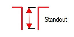
We measure the standout of the nozzle where Radar (Horn type) has to be installed.

Then we ensure that the Horn protrudes out of the nozzle and is not within the Nozzle

How do we measure standout?

From Center of Nozzle to face of flange we extract the distance.

And then add a safety margin of 1 or 2 mm and decide the length

Refer Below pics (simple nozzle)

Simple Nozzle for Radar Level Transmitter

It looks so simple, what can possibly be tricky in this.

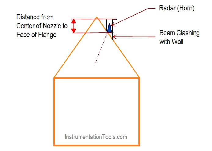
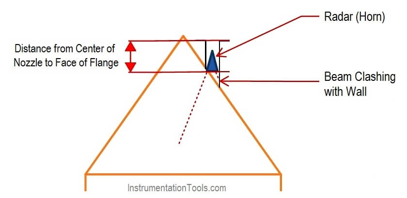
Now let’s look at sloping tank and its corresponding nozzle.

This happens where the Slope is High.

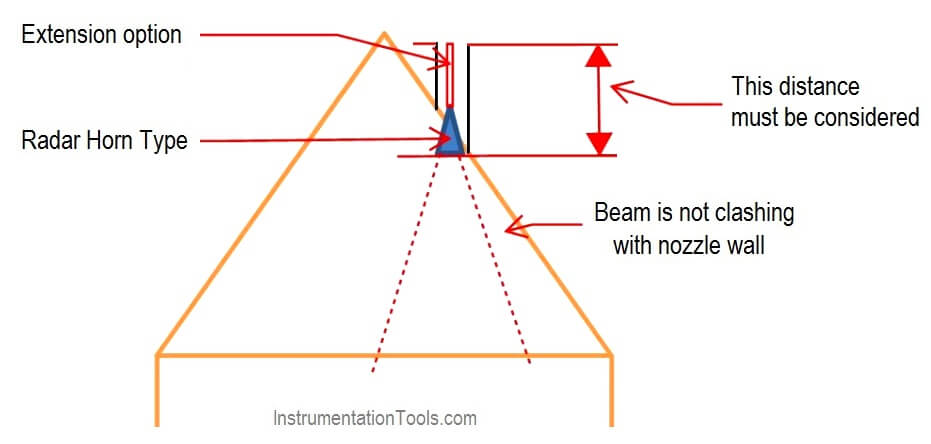
If We measure from here then The Waves Emitted from Radar will clash with nozzle

Refer Pic Below

Horn Type Radar Level Transmitter

Radar Level Transmitters Installation on Slopping Tank

A close-up picture

Radar Transmitters Installation Problems

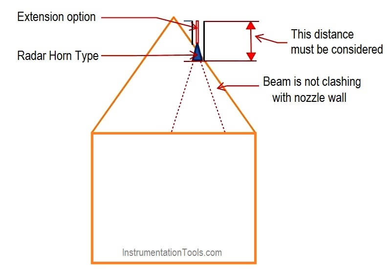
Hence for such cases, the length must be calculated from the longer side of nozzle to FOF (Face of Flange)

Refer Pic Below

Radar Transmitter Installation

A close up Pic

Slop Tank Level Transmitter Erection

Also, Note for cases where the standout is more, Extensions can be used to increase the length of horn such that the waves from the horn do not clash with the Nozzle wall.

If the Slope is less, this can be neglected but where the slope is High it has a great significance!!

Thanks for Reading!

PS: This is as per the best of my current understanding.

Credits:- Thanks to Rupali Gawde & Satish Sohani

Join the Discussion

Share & leave us some comments on what you think about this topic or if you like to add something.

Author : Asad Shaikh

Profile : Linkedin

Articles You May Like

Radar Level Transmitter in Briddle

Guided-wave Radar Animation

Non Contact RADAR Installation

Radar Level Measurement Guide

Diagnostics of Level Transmitters
Don't Miss Our Updates
Be the first to get exclusive content straight to your email.
We promise not to spam you. You can unsubscribe at any time.
Invalid email address
You've successfully subscribed !

Recommended Articles

Non Contacting Radar Level Transmitter Animation
Non-Contacting Radar Level Transmitter Working Principle
What is Double Block and Bleed Valves?
What is Dip Tape Level Measurement?
How to Solve Cable Tray Sagging ?
Interface Level Measurement Selection Guide
Share This Article
Facebook Whatsapp Whatsapp LinkedIn Copy Link
Share
1 Comment
  • Rohit makvana says:
    August 30, 2019 at 8:04 am

    Sir, u R doing great job……

    Reply

Leave a Reply Cancel reply

Your email address will not be published. Required fields are marked *

Stay Connected

128.3kFollowersLike
69.1kFollowersFollow
208kSubscribersSubscribe
38kFollowersFollow

Categories

Recent Comments

  • William Snyder on Top Non-PLC Certification Courses for Automation Professionals
  • Kamli on Top Free PLC Software
  • Guifty Shimica on Top Non-PLC Certification Courses for Automation Professionals
  • Guifty Shimica on Top Non-PLC Certification Courses for Automation Professionals

Related Articles

Instrumentation Cables Armor

Instrumentation Cables Armor

Asymmetric capillary for Level Measurement

Effects of Symmetric and Asymmetric Capillary Tube Pressure Measurement

Turbine Flow Meter Installation Procedure

what-is-o-ring

What is an O-Ring?

Level Gauge Theory

Types of Level Gauges

Closed Tank Remote Seal Level Transmitter calculation

Remote Seal Transmitters Ranging Calculation

Ultrasonic Level Transmitters Installation
Ultrasonic Level Transmitter Principle, Limitations, Calibration and configuration

Multiple Thermowell Installations Problems

Multiple Thermowell Installations Problems

More Articles

Simple Conveyor Control PLC Program

XG5000 Example of Simple Conveyor Control PLC Program

Site Acceptance Test (SAT) of PLC System

PLC System Site Acceptance Test (SAT)

Measurement of Errors Objective Questions

Measurement of Errors Objective Questions

Sling Psychrometer Principle

Sling Psychrometer Principle

solenoid-valves-types-principle-animation

Solenoid Valves Types, Principle & Animation

Digital Circuits Questions & Answers

Digital Circuits Questions & Answers

Calibration of Temperature Sensor with Indicator

Calibration of Temperature Sensor with Indicator

Formula of 2 Wire RTD, 3 Wire RTD & 4 Wire RTD

Formula of 2 Wire RTD, 3 Wire RTD & 4 Wire RTD

Follow US
All rights reserved. Reproduction in whole or in part without written permission is prohibited.
Welcome Back!

Sign in to your account

Username or Email Address
Password

Lost your password?