By using this site, you agree to the Privacy Policy and Terms of Use.
Accept
Inst ToolsInst ToolsInst Tools
  • Ask
  • Courses
  • Videos
  • Q & A
    • Interview
      • Instrumentation
      • Electronics
      • Electrical
      • Practical Questions
    • MCQ
      • Instrumentation MCQ
      • Electrical MCQ
      • Electronics MCQ
      • Control Systems MCQ
      • Analog Electronics MCQ
      • Digital Electronics MCQ
      • Power Electronics MCQ
      • Microprocessor MCQ
      • Multiple Choice Questions
  • EE
    • Electronics
      • Electronics Q & A
      • Electronic Basics
      • Electronic Devices & Circuits
      • Electronics Animation
      • Digital Electronics
    • Electrical
      • Electrical Basics
      • Electrical Q & A
      • Power Electronics
      • Electrical Machines
      • Electrical Animation
      • Power Systems
      • Switchgear & Protection
      • Transmission & Distribution
  • Measure
    • Control Valves
    • Calibration
    • Temperature
    • Pressure
    • Flow
    • Level
    • Analyzers
    • Switches
    • Vibration
    • Solenoid Valve
  • Control
    • PLC Tutorials
    • Control Systems
    • Safety Instrumented System (SIS)
    • Communication
    • Fire & Gas System
  • More
    • Design
    • Tools
    • Animation
    • Basics
    • Formulas
    • Standards
    • TextBooks
    • Common
    • Software
    • Excel Tools
    • Erection & Commissioning
    • Process Fundamentals
    • Videos
    • Books
Search
All rights reserved. Reproduction in whole or in part without written permission is prohibited.
Reading: Why we Require Dual SOV on a Control Valve?
Share
Notification Show More
Font ResizerAa
Inst ToolsInst Tools
Font ResizerAa
  • Ask
  • Courses
  • Videos
  • Q & A
  • EE
  • Measure
  • Control
  • More
Search
  • Ask
  • Courses
  • Videos
  • Q & A
    • Interview
    • MCQ
  • EE
    • Electronics
    • Electrical
  • Measure
    • Control Valves
    • Calibration
    • Temperature
    • Pressure
    • Flow
    • Level
    • Analyzers
    • Switches
    • Vibration
    • Solenoid Valve
  • Control
    • PLC Tutorials
    • Control Systems
    • Safety Instrumented System (SIS)
    • Communication
    • Fire & Gas System
  • More
    • Design
    • Tools
    • Animation
    • Basics
    • Formulas
    • Standards
    • TextBooks
    • Common
    • Software
    • Excel Tools
    • Erection & Commissioning
    • Process Fundamentals
    • Videos
    • Books
Follow US
All rights reserved. Reproduction in whole or in part without written permission is prohibited.
Inst Tools > Blog > Control Valves > Why we Require Dual SOV on a Control Valve?

Why we Require Dual SOV on a Control Valve?

Last updated: July 21, 2020 12:18 pm
Editorial Staff
Control Valves Guest Articles
7 Comments
Share
5 Min Read
SHARE

Solenoid valves are often used in some applications in which a control valve under certain conditions requires where it quickly was driven to the fail position.

Contents
SolenoidWhy we require Single SOV on a Control Valve?Why we require Dual SOV on a Control ValveDual SOV circuits:Case 1: When SOV-1 become a failure in this condition then what will happen:Case 2: When SOV-2 becomes a failure in this condition then what will happen:-Case-3: When both SOV become de-energiesHow to check SOV Healthiness in running plant:Read Next:

Solenoid valves are usually electrically actuated on-off or three-way valves installed into the air system and designed to take a specific action when tripped.

Solenoid

SOV SCHEMATIC

The solenoid can be thought of as an on-off switch for a pneumatic system.

The signal to the solenoid controls the action of the internal valve assembly, allowing flow through the valve in one position and in other position isolating or venting the air.

Dual Solenoid Valves on Control Valve

Why we require Single SOV on a Control Valve?

For example, there is a control valve which requires quick action in the fail-safe condition in emergency situations, then a  2 way SOV is installed between Positioner output and Actuator inlet.

When the SOV is energized condition then SOV inlet connected to the outlet and allowing air to flow from Positioner output to the actuator.

When SOV is in de-energized condition then output is connected with vent (Exhaust port) and its venting the control valve air from exhaust port quickly and moving the valve to the fail-safe position.

Why we require Single SOV on a Control Valve

Why we require Dual SOV on a Control Valve

In some cases, it has been found out that due to SOV failure (SOV may fail due to many reasons like Coil open, fuse blown, Plunger stuck up, passing in SOV, etc) control valve goes to fail-safe condition and its leads to trip the plant due to closing /opening the valve or may cause some unwanted process disturbances.

As the shutdown of the plant goes very expensive, so dual SOV philosophy comes for redundancy purposes.

In dual SOV, if one SOV fails then the plant will not disturb.

Dual Solenoids on a Control Valve 

Dual SOV circuits:

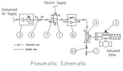
Dual SOV pneumatic schematic shows in the below Figure.

Suppose that Air continuously going to the actuator in normal condition.

Positioner output is connected in both SOV inlet, SOV-1 outlet is connected to SOV-2 exhaust and final output goes from SOV-2 to the actuator.

Case 1: When SOV-1 become a failure in this condition then what will happen:

When SOV-1 become failure

If SOV-1 is going failure then the SOV-1 output port is connected with exhaust and air is going from SOV-2 because SOV-2 is energized and the inlet is connected to the output.

Air Flow indications are shown in the above figure with the arrows.

Case 2: When SOV-2 becomes a failure in this condition then what will happen:-

When SOV-2 becomes failure

If SOV-2 becomes failure then the SOV-2 outlet is connected with exhaust and SOV-1 is energized then the air goes from SOV-1 inlet to outlet then outlet is connected with SOV-2 exhaust which is connected with SOV-2 outlet in fail condition and the air is going to actuator.

Air Flow indications are shown in the above figure with the arrows.

Case-3: When both SOV become de-energies

When both SOV become de-energies

When both SOV is de energies then both SOV outlet is connected with exhaust and block the inlet then actuator air is released from SOV-2 outlet to exhaust then exhaust is connected with SOV-1 outlet and SOV-1 outlet connected with exhaust and air is released.

Air Flow indications are shown in the above figure with the arrows.

How to check SOV Healthiness in running plant:

Check the monthly surface temperature of SOV by the pyrometer. if both SOVs are from the same company then the surface temperature is almost equal. (Max difference between both SOV is 5 deg c). If the temperature difference is more then check the coil resistance.

Check physically the exhaust port that air is blocked or in normal condition.

Sponsored: Solenoid-valve.world

Author: Ashish Agrawal

Read Next:

  • Control Valves MCQ
  • Solenoid Valve Wiring to PLC
  • Types of Valve Accessories
  • Solenoid Manual Override
  • Online Testing of SOV
Don't Miss Our Updates
Be the first to get exclusive content straight to your email.
We promise not to spam you. You can unsubscribe at any time.
Invalid email address
You've successfully subscribed !
Flow Control Valves Interview Questions
What is a Pneumatic Cylinder?
Butterfly Valves Construction, Types, Stem & Bonnet Assembly
Circular Chart Recorder Calibration Procedure
Difference between PT100, PT1000, Nickel RTD and Balco RTD
Share This Article
Facebook Whatsapp Whatsapp LinkedIn Copy Link
Share
7 Comments
  • shabbir says:
    January 18, 2018 at 5:44 am

    no any data about absolute presure transmitters and gauges???

    Reply
    • S Bharadwaj Reddy says:
      January 18, 2018 at 5:58 am

      Please check in “Pressure Measurement” category

      Reply
  • Salah says:
    March 31, 2018 at 6:48 am

    What is the ordinary value of thd sov coil that should be found when checking ?

    Reply
    • Andrzej says:
      June 11, 2018 at 12:41 pm

      Depends on sov, please look at the resp. data-sheet. Usually the power is shown.

      Reply
  • Rakesh Hasmukhlal Sagar says:
    January 3, 2019 at 3:08 pm

    please show dry calibration calculation for single and interface level troll

    Reply
  • Hamid Ali says:
    January 3, 2019 at 4:46 pm

    A great and useful study centre of instrumentation field…i really appreciate that to its honour.

    Reply
  • Kamesh says:
    February 21, 2019 at 9:26 pm

    In this article both sovs are de energised due to problem & you tell air was released from actuator &inlet air blocked
    But in that time my control valve do not close that means not to disturb the valve
    What we will do?

    Go to another sov…?

    Reply

Leave a Reply Cancel reply

Your email address will not be published. Required fields are marked *

Stay Connected

128.3kFollowersLike
69.1kFollowersFollow
208kSubscribersSubscribe
38kFollowersFollow

Recent Comments

  • MIHARITSOA Aina Sitraka on Top Non-PLC Certification Courses for Automation Professionals
  • Vaishnavi on Free Instrumentation Course for Trainee Engineers
  • anuj kapoor on DCS Program to Maintain Draft in Furnace
  • anuj kapoor on IoT based Smart Boiler Control System with Cloud PLC and SCADA

Related Articles

3-way directional control valves

Directional Control Valves Working Principle

DIN Valve Connectors

DIN Valve Connectors – Definition, Types

Choked Flow of Control Valve

Choked Flow of Control Valves

Pressure Gauges Common Problems

Pressure Gauges : Common Causes for Failures and Their Effective Solutions

Control Valve Tips and Tricks

Control Valve Tips and Tricks

Air Lock Relay Working Principle

Control Valve Air Lock Relay Working Principle

Root Cause Analysis on Hunting of Control Valves

Hunting of Control Valves

FDA Process Validation

Why You Need FDA Process Validation and How to Do It Right ?

More Articles

Calibration Instruments

Basics of Calibration

Namur Digital Input Card

What is Namur Digital Input Card?

Battery in Vehicle

Why is a Battery used in a Vehicle?

Why rating of Synchronous Generators and Alternators in MVA or KVA

Thermowell-Insertion-and-Immersion-Length

What is a Transformer Tap Changer

State Variable Analysis and Design

Concepts of State, State Variables & State Model

DP Diaphragm Capillary Seal Level instrument

DP Diaphragm Capillary Seal Level instrument Calibration Procedure

Digital Transducers Objective Questions

Digital Transducers Objective Questions

Follow US
All rights reserved. Reproduction in whole or in part without written permission is prohibited.
Welcome Back!

Sign in to your account

Username or Email Address
Password

Lost your password?