VFD simulator download: Master the online tool from the Yaskawa V1000 & programming software for variable frequency drive testing.
This article is an educational resource for mastering VSD (Variable Speed Drive) devices and learn the Yaskawa V1000 Programming Simulator.
When working with VFD (Variable Frequency Drive), we face limitations due to the lack of hardware or apprehensions about potential errors and faults when experimenting directly on physical drives.
As a solution, this article outlines the process of operating and adjusting the electric motor speed on VSD (Variable Speed Drive) using the VFD simulator software.
What is a VFD?
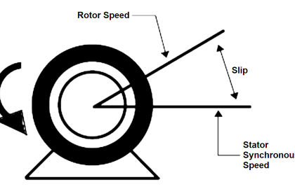
Before learning the steps of using VFD (Variable Frequency Drive), it would be better for us to learn about what VFD is. VFD stands for Variable Frequency Drive, which is an electronic device that can control the speed of an asynchronous motor or the speed of a synchronous motor by varying the frequency.
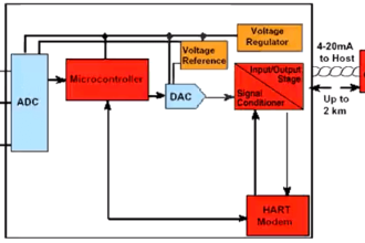
The working principle of VFD or Variable Frequency Drive uses three steps, namely;
Converter – In this Converter section, there will be a process of changing the AC voltage input into DC voltage.
DC-Link – On the DC-link section this will flatten the ripples of the DC current wave.
Inverter – This inverter will convert DC voltage into AC voltage. The AC voltage produced is not a pure sine wave but is based on the PWM principle or Pulse Width Modulation which is the general principle of inverter technology.
VFD Simulator Download
This video explains how to download the free VFD simulator and how to use the simulation tools.
Yaskawa Simulator V1000 Programming Tool
Simulator V1000 Programming is a VFD simulation software from Yaskawa America, Inc.
In this software, we can practice how to setup VFD parameters and use them simulated, with the motor simulation animation feature that can make us see the results of parameter settings on motor performance.
In Simulator V1000 Programming we can simulate analog Input settings, Digital Input, Analog Output, Pulse Input, Pulse Output, and many other parameter settings.
This software is also equipped with a Digital Operator display that allows us to find out how the VFD Digital Operator actually looks.
How To Set Up and use the Yaskawa V1000 Simulator?
Before carrying out the simulation procedure, it is expected to have downloaded the Yaskawa V1000 Programming Simulator Software from the official Yaskawa Web.
Here we will learn the basic settings of the VFD, namely about how to run the VFD and adjust the speed of the 3-phase electric motor from the VFD.
Step-One
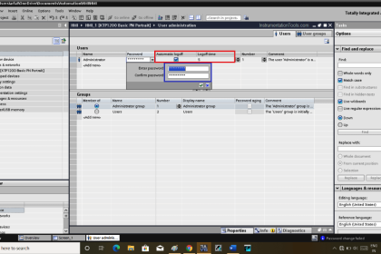
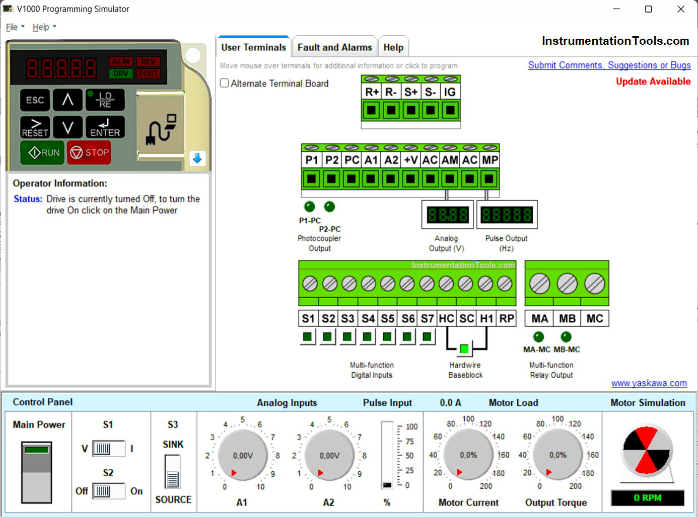
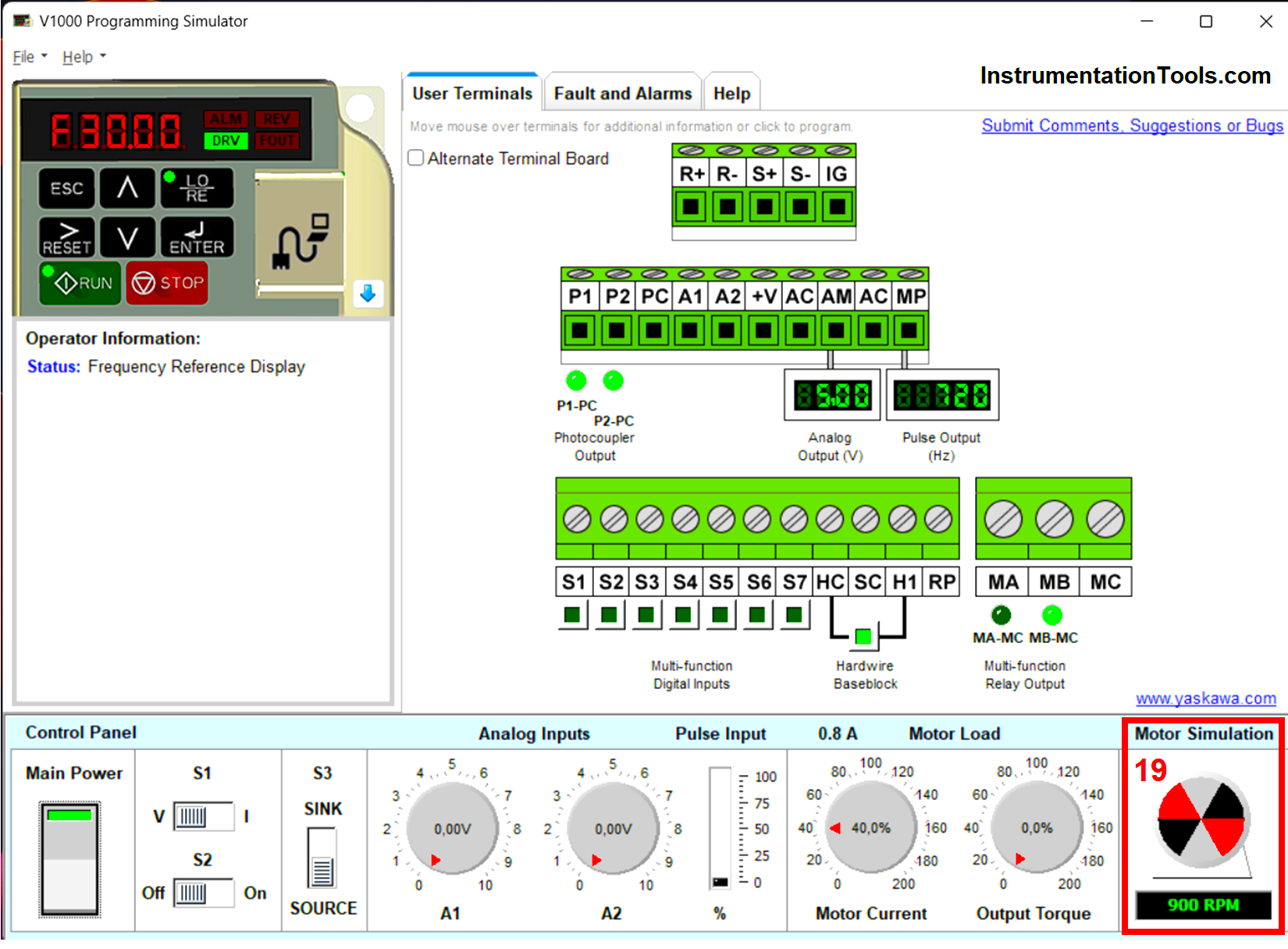
Open the installed Yaskawa V1000 Programming Software Simulator, here is the interface of the simulator.
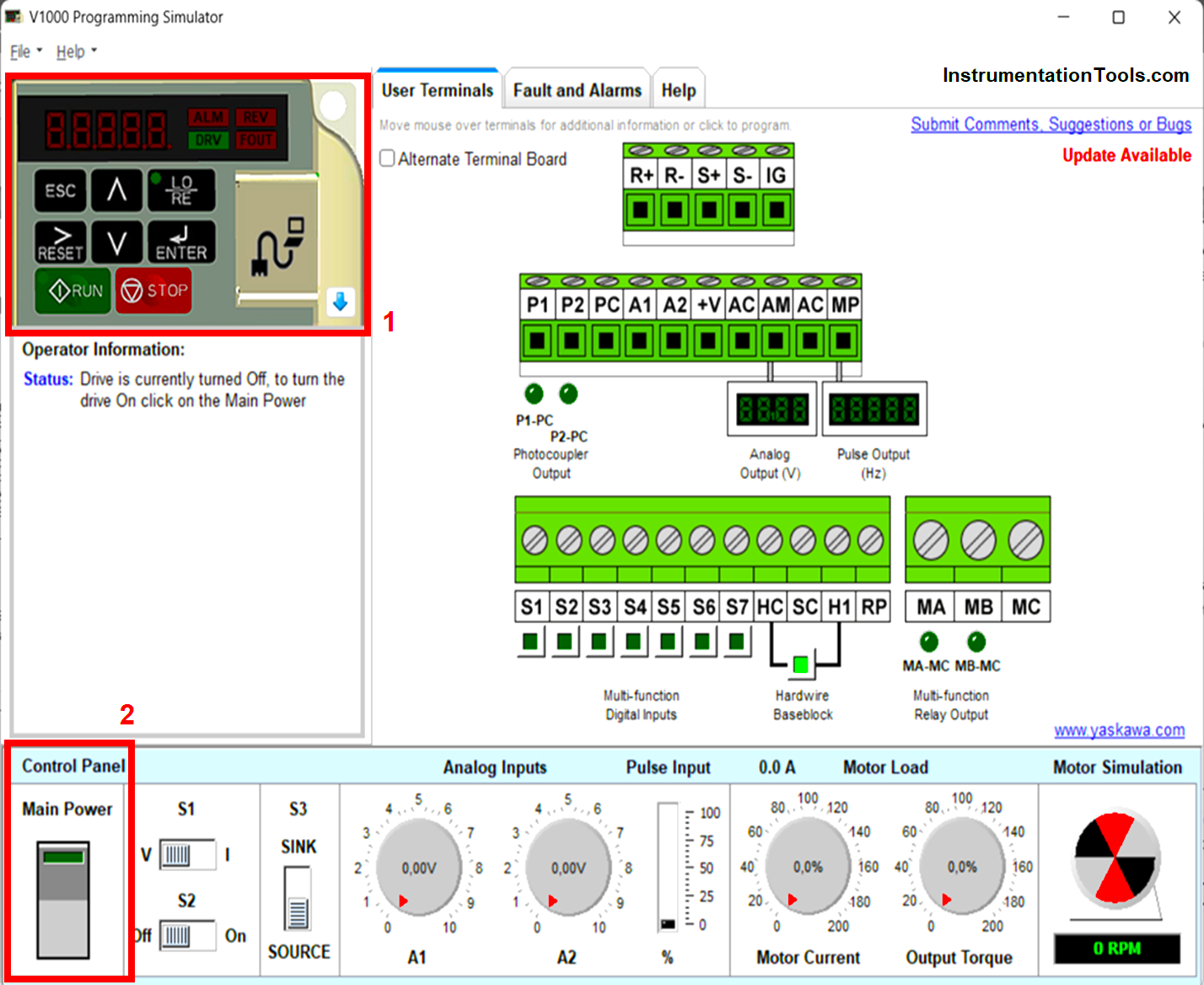
In the Yaskawa V1000 Programming Simulator Interface display above, we can see the Digital Operator area (red box no.1) which is the same as the original display/hardware of the Yaskawa V1000 VFD.
The Digital Operator serves as a medium to enter the parameters of the VFD and also as a Local controller when the VFD is run in Local mode.
To start we need to turn on the VFD simulator by pressing the Main Power button (red box no.2).
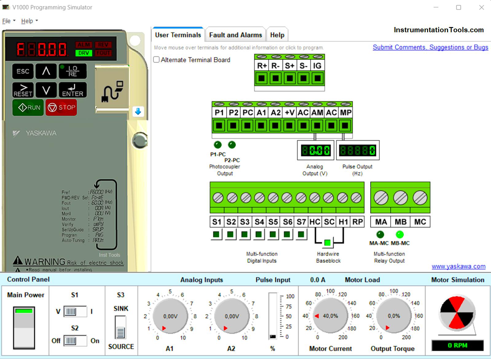
When the system is on, some indicators on the Interface will light up as shown above and on the Main Power button the light indicator will light up green.
Step-Two
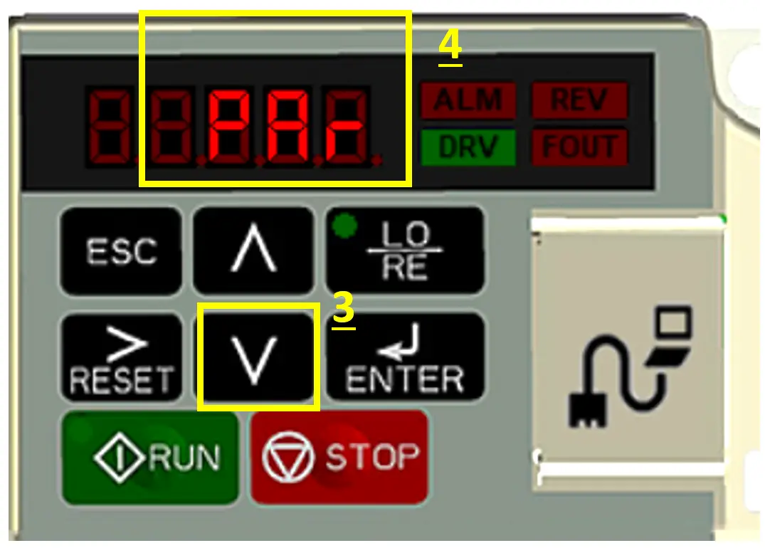
Enter at the initial stage of setting parameters, click the down button 2x (yellow box no.3) or until the appearance of the character “Par” (yellow box no.4) then click the Enter button.
Step-Three
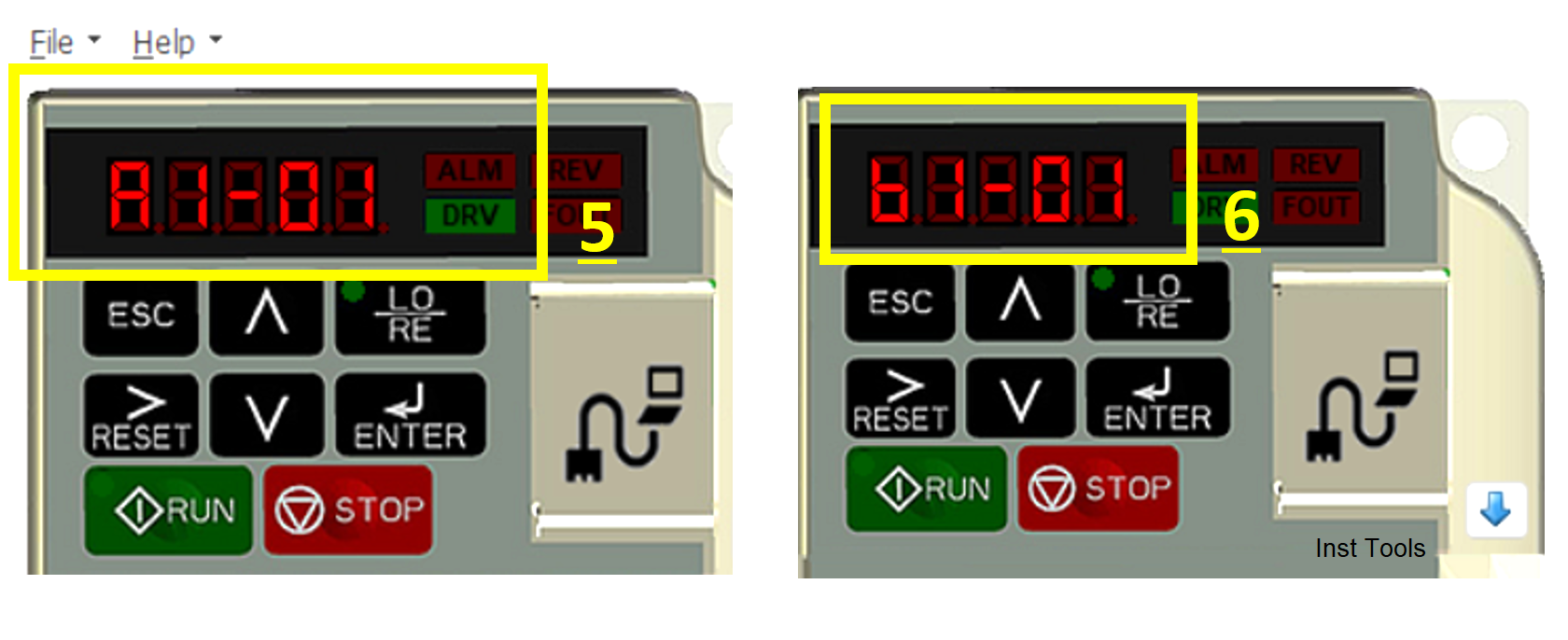
Then the parameter display will change to the following (yellow box no.5), click the UP button again until the parameter changes to “b1-01” (yellow box no.6) from the original “A1-01”.
The parameter “b1-01” serves to set the method of regulating motor speed, which can be for Local mode, External mode (analog signal), and External Pulse mode.
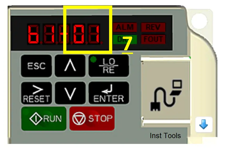
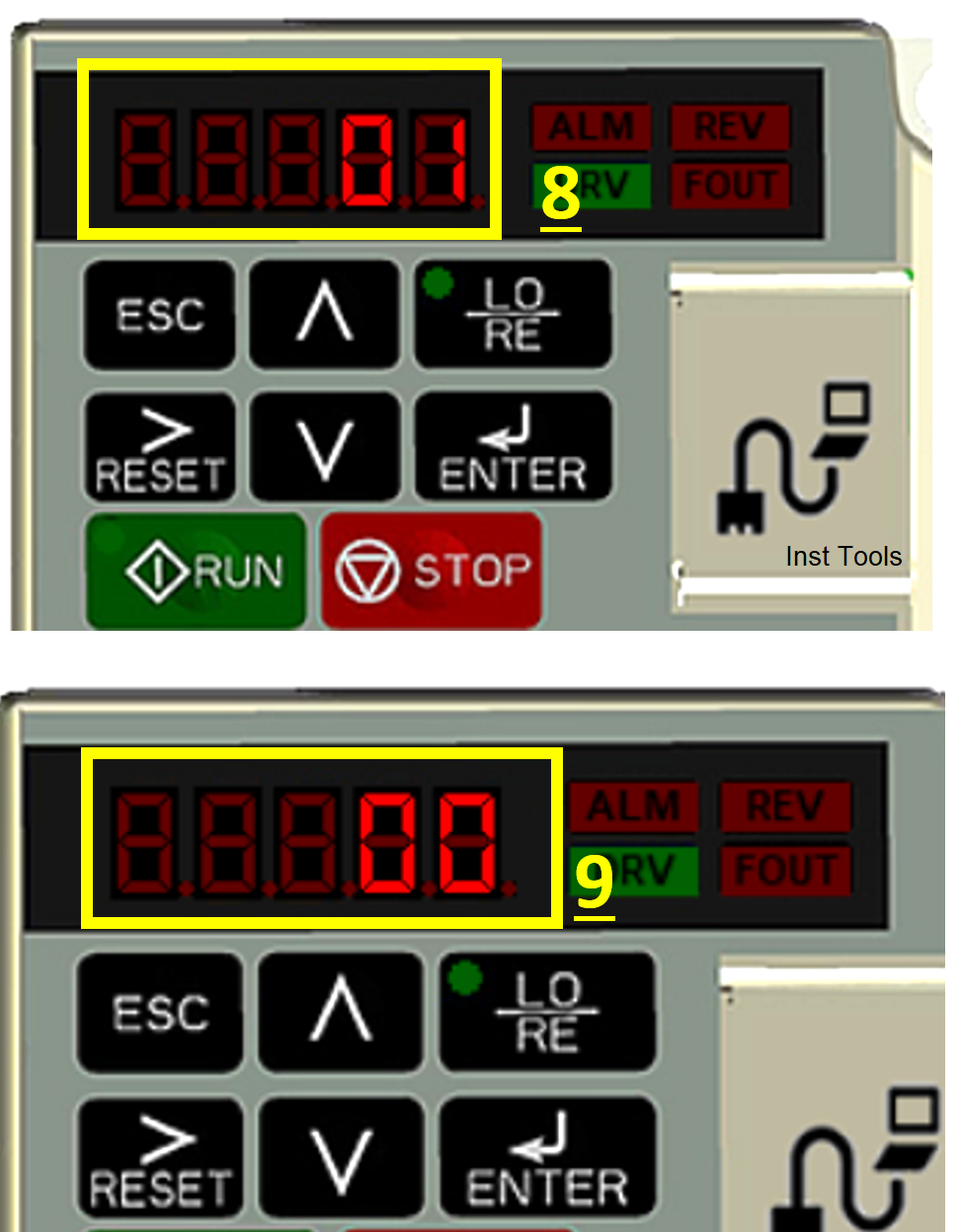
When the parameter shows “b1-01” click the Reset button several times until the display number “01” flashes (yellow box no.7) then click Enter.
Next, the Parameter display will change as follows (yellow box no.8), click the UP/down button to change the parameter.
Change it to “00” (yellow box no.9) means that the motor speed regulation uses Local mode, local mode means we vary the VFD frequency value through the Digital Operator. Then click Enter
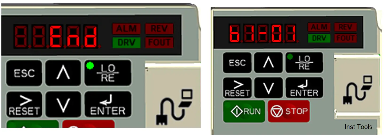
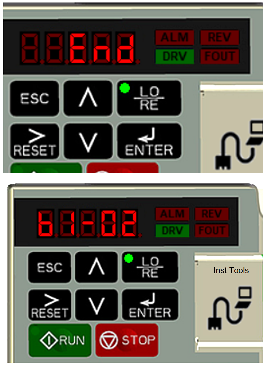
The Parameters display will display the character “END” for a moment which means the change of mode is successful, then it will automatically return to the display of the parameter “b1-01” as shown below.
Step-Four
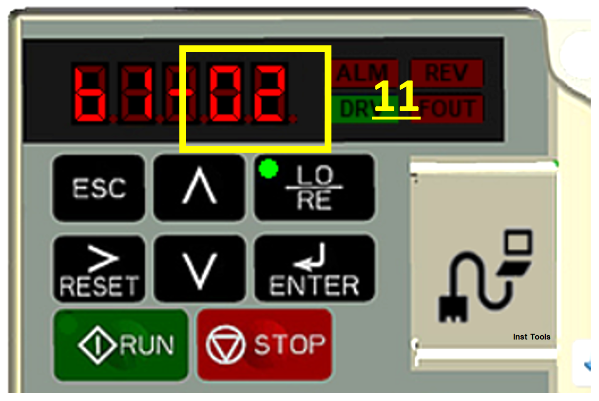
In the fourth step, we need to enter the parameter “b1-02”, which is a parameter that functions as a setting mode for turning on and off the motor locally or externally.
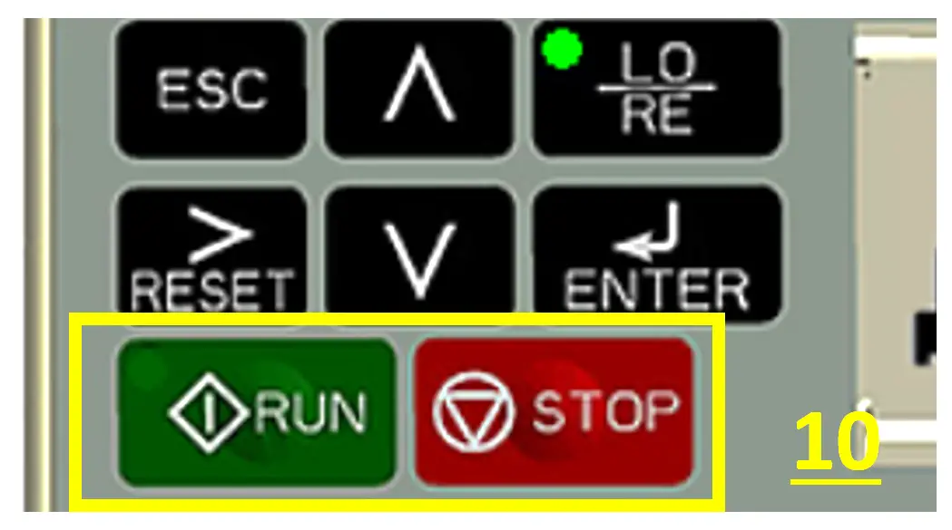
Local mode means that we turn on the motor via the “RUN” button on the Digital Operator and turn off using the “STOP” button on the Digital Operator (yellow box no.10).
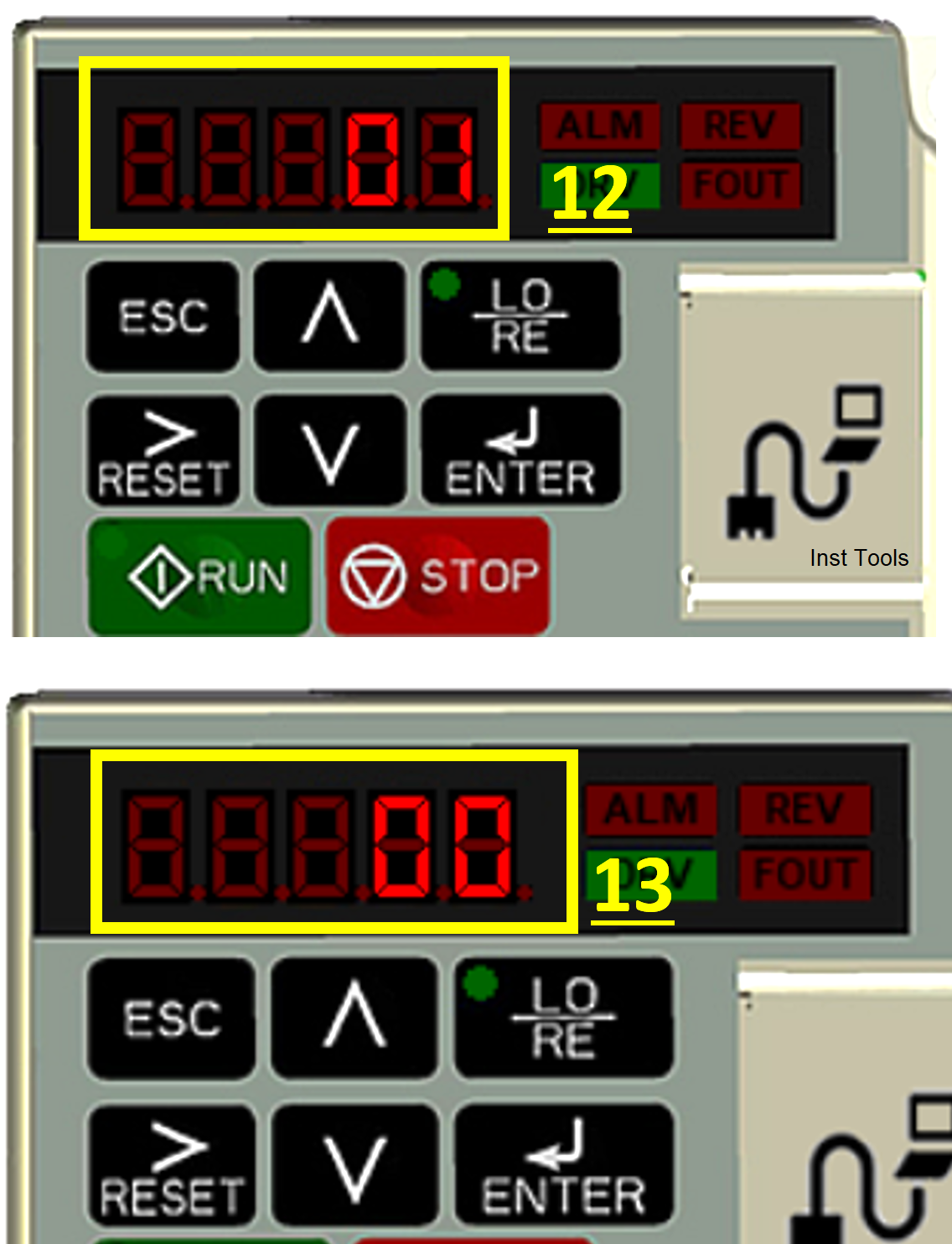
Click the UP/down button until the original parameter “01” becomes “02” as shown below (yellow box no.11). Then click the Enter key again.
The Parameters display will change again and then change the previous value “01” (yellow box no.12) to the value “00” (yellow box no.13) by pressing the UP/Down button.
Then click Enter.
The Parameters display will display the character “END” for a moment which means the change of mode is successful, then it will automatically return to the parameter display “b1-02” as shown below.
Mode Setup Process Complete
Step-Five
The next step is simulation. Click the “ESC” button several times (yellow box no.14) to return to the “F 000” home menu (yellow box no.15).
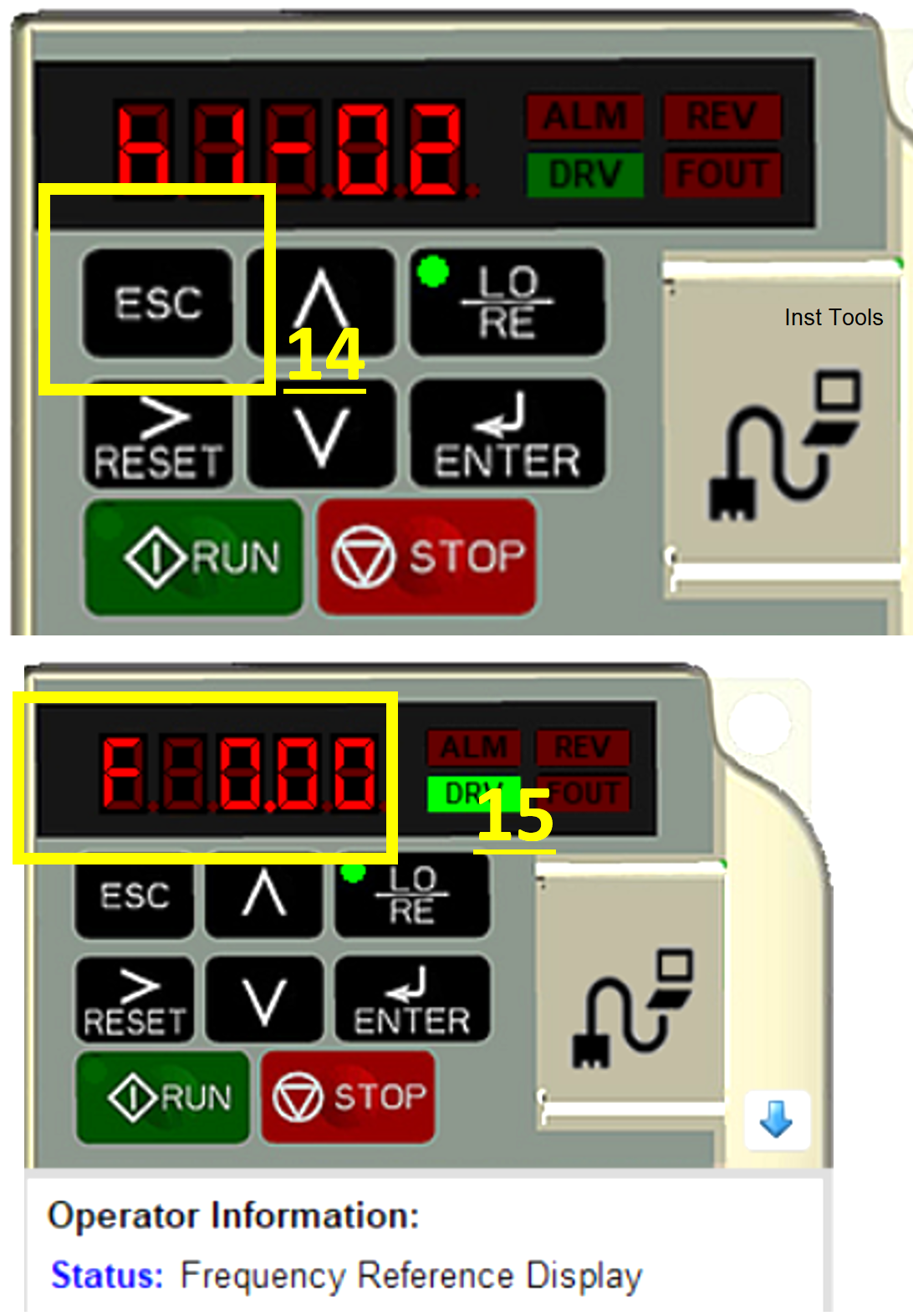
The parameter “F 000” is a frequency parameter that we can modify its value to regulate the speed of the motor.
Then click the Enter key until the parameter “F 000” flashes and the display changes to “F00.00” (yellow box no.16).
Change the Frequency value to the value you want by pressing the UP/Down button to modify the value and the “RESET>” button to shift to the value or parameter to be modified.
For example, the motor is run with a frequency of 30 Hz (yellow box no.17). then click Enter.
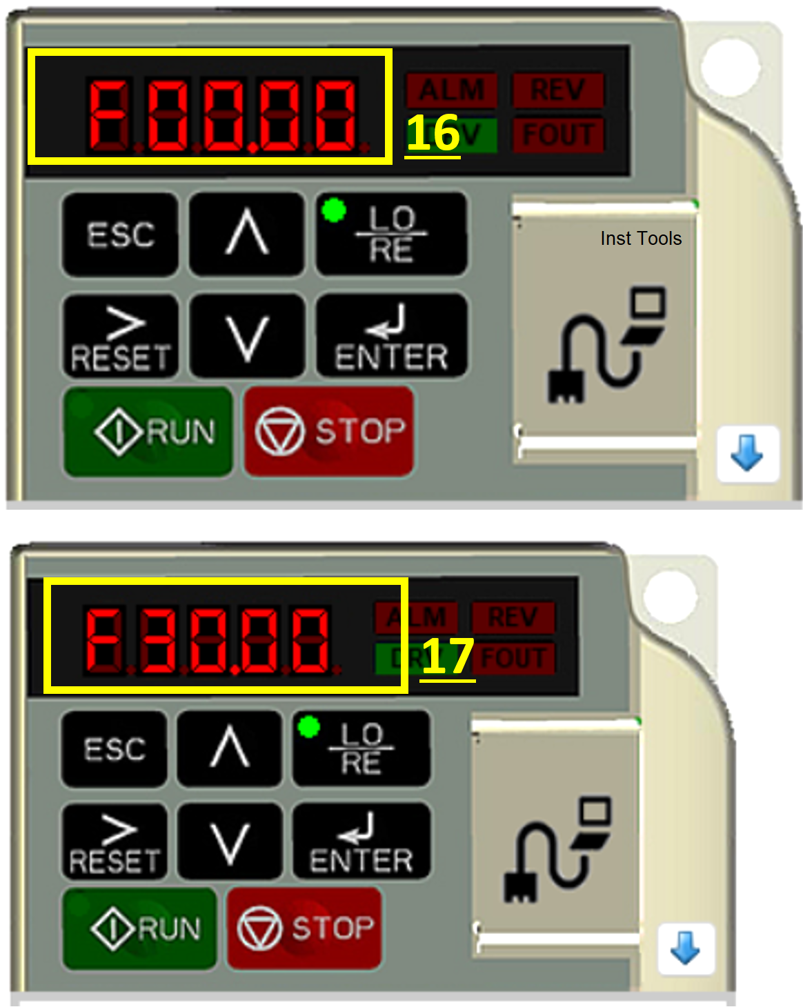
Display Parameters will be “END” while the display will change The “DRV” indicator (yellow box no.16) will light up, meaning the VFD is ready to run.
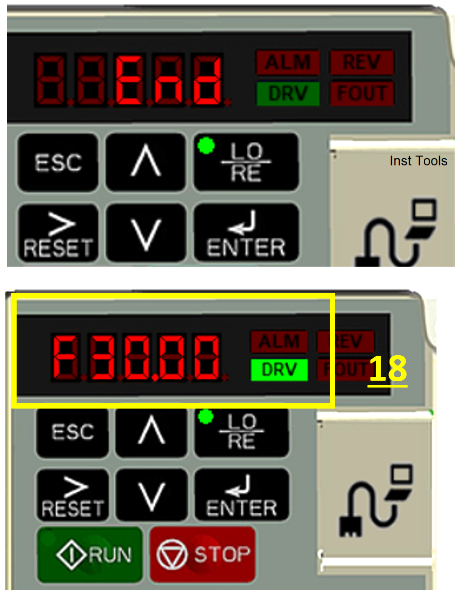
Click the RUN button to run the motor then observe the motor simulation animation that will move and display the RPM value (red box no.19) as shown below.
We can also observe the Analog output and Pulse Output indicators that output Output values. Click the STOP button to stop the motor.
The simulation procedure using Yaskawa V1000 Programming Simulator Software has been completed.
References
- Variable Frequency Drive or VFD in Industrial Automation, PT. Proweb Indonesia.
- Yaskawa.Inc.
If you liked this article, please subscribe to our YouTube Channel for PLC and SCADA video tutorials.
You can also follow us on Facebook and Twitter to receive daily updates.
Read Next:
- Communicating Delta PLC Software to Simulator
- How to use a Simulator in Siemens PLC Software?
- Automatic Car Washing using PLC Programming
- PLC Programming for Defective Parts Sorting
- PID Controller Tuning Parameters Simulator