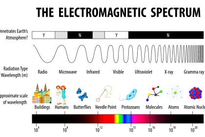
The electromagnetic wave spectrum existing around us consists of many waves with their corresponding frequencies and wavelengths. Two of the most high frequencies available used in many applications are microwaves and radio.
Due to their wavelength and frequency properties, they are apt for use in many areas of work; so they have contributed a lot to science and physics. Microwave or RF design and test circuits consist of a device that is required compulsorily in it – an isolator.
In this post, we will see the use of an isolator in microwave and radio frequency applications.
What is an Isolator?
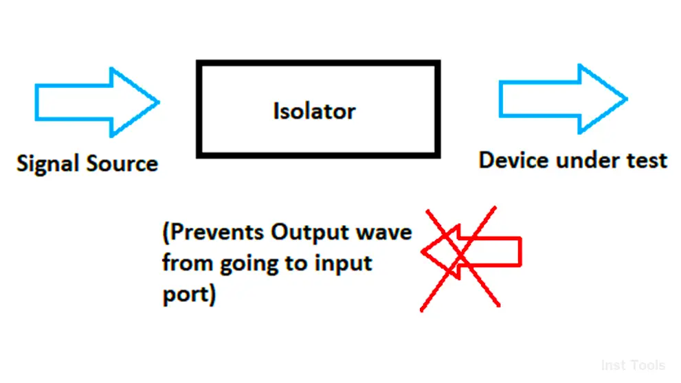
An isolator is an equipment that is used in microwave and RF test bench applications to prevent output waves from going into the input port side; thus preventing the signal source from damage. If you thus see it, you find it as non-reciprocating (moving in only one direction) and passive (which only consumes energy and not produces it).
Isolators are non-reciprocal devices, meaning their behavior in one direction is very different from that in the other direction.
First, let us understand the basics of waveguides. Without going deeper, we will directly come to the application basics. The signal through a waveguide is propagated by different modes which are denoted by TE (transverse electric) mode.
The alignments between electric and magnetic fields relate to the modes used for propagation; and when the electric field of the signal is perpendicular to the direction of propagation through a waveguide, it is called TE mode. In this mode, the magnetic field components are in the direction of propagation.
One of the most generally used modes is the TE10 mode. In this mode, the wavelength is λ/2 of the electric field and λ/4 of the magnetic field. It means that during propagation through the waveguide, the electric field is perpendicular to the direction of propagation.
Now, let us come back to our topic by referring to the below image. An input port of the isolator consists of a TE10 waveform. When the input is given through the input port, the same wave will be reflected in the output port; but if the input is given through the output port, then the output at the input port will be zero. So how this works?
Basically, a resistive card is present in the input port. The input signal is given in the way of vertically polarized form, which the resistive card will not absorb. But, the output signal is fed to the card in the horizontally polarized form, which the resistive card will absorb. This prevents the output signal from going into the input port.
Use of Isolator in Microwaves
When the device is under testing at the output port, there is a chance of unwanted reflections coming from them. If this reflection is mistakenly passed to the input port where the signal source is present, then it can damage the equipment.
Often, high voltage or current amplifiers are present on the input side, and if the spikes and reflections reach them, then the amplifier can get damaged quickly. So, an isolator is required between the input and output port, to isolate both the circuits and prevent the input port from damage.
Practically, the isolator is connected between a signal generator and some device under test (DUT). You may have heard the term – VSWR (voltage standing wave ratio) in antenna studies; which determines the impedance ratio between an antenna and a radio. If the difference is low, then the impedance is mostly matching and there are good chances of perfect communication; but if the impedance difference is high, then it is bad communication and there are more chances of reflected waves.
The isolator absorbs this signal, protecting the usually expensive signal generator. What the isolator does is due to its construction, only one path of energy for RF waves is designated. The waveform entering from the opposite side is dissipated as heat as there is no path of energy for the waves to flow. This means that there is heavy attenuation for the RF signal entering from the output port. Thus, the device is protected from damage.
If you liked this article, then please subscribe to our YouTube Channel for Instrumentation, Electrical, PLC, and SCADA video tutorials.
You can also follow us on Facebook and Twitter to receive daily updates.
Read Next:
- What is a Ground Rod?
- Types of Stepper Motors
- What is an Inductor?
- What is Data Acquisition?
- Safety Automation System