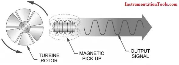
Turbine Flow Meter is a volumetric measuring turbine type. The flowing fluid engages the rotor causing it to rotate at an angular velocity proportional to the fluid flow rate.
The angular velocity of the rotor results in the generation of an electrical signal (AC sine wave type) in the pickup. The summation of the pulsing electrical signal is related directly to total flow.
The frequency of the signal relates directly to the flow rate. The vaned rotor is the only moving part of the flow meter.
Turbine Flow Meter
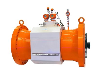
The Turbine flow meter (axial turbine) was invented by Reinhard Woltman and is an accurate and reliable flow meter for liquids and gases. It consists of a flow tube with end connections and a magnetic multi-bladed free-spinning rotor (impeller) mounted inside; in line with the flow. The rotor is supported by a shaft that rests on internally mounted supports.
The Supports in Process Automatics Turbine Flow Meters are designed to also act as flow straighteners, stabilizing the flow and minimizing the negative effects of turbulence.
The Supports also house the unique open bearings; allowing for the measured media to lubricate the bushes – prolonging the flow meter life span. The Supports are fastened by locking rings (circlips) on each end.
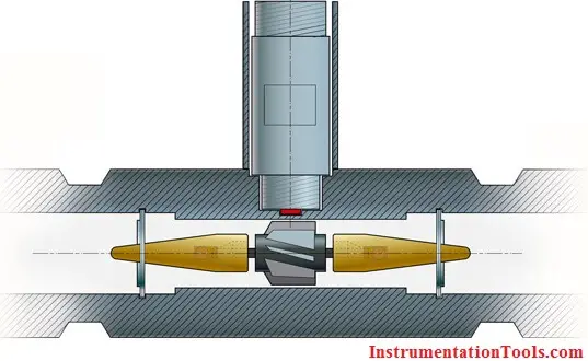
The rotor sits on a shaft, which in turn is suspended in the flow by the two supports. As the media flows, a force is applied on the rotor wings. The angle and shape of the wings transform the horizontal force into a perpendicular force, creating rotation. Therefore, the rotation of the rotor is proportional to the applied force of the flow.
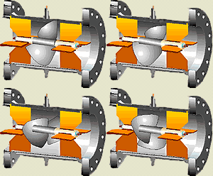
Because of this, the rotor will immediately rotate as soon as the media induces a forward force. As the rotor cannot turn through the media on its own, it will stop as soon as the media stops. This ensures an extremely fast response time, making the Turbine Flow Meter ideal for batching applications.
A pick-up sensor is mounted above the rotor. When the magnetic blades pass by the pickup sensor, a signal is generated for each passing blade. This provides a pulsed signal proportional to the speed of the rotor and represents pulses per volumetric unit.; and as such the flow rate.
Also Read: Flow Meters Troubleshooting Tips
Applications of Turbine Flow Meters
In order of magnitude from largest to smallest,
- these are used in oil and gas,
- water and wastewater,
- gas utility,
- chemical,
- power, food, and beverage,
- aerospace, pharmaceutical,
- metals and mining, and pulp and paper.
Cautions for Turbine Flow meters
Turbine meters are less accurate at low flow rates due to rotor/bearing drag that slows the rotor. Make sure to operate these flow meters above approximately 5 percent of maximum flow. Turbine flow meters should not be operated at high velocity because premature bearing wear and/or damage can occur.
Be careful when measuring fluids that are non-lubricating because bearing wear can cause the flow meter to become inaccurate and fail. In some applications, bearing replacement may need to be performed routinely and increase maintenance costs.
Application in dirty fluids should generally be avoided so as to reduce the possibility of flow meter wear and bearing damage. In summary, turbine flow meters have moving parts that are subject to degradation with time and use.
Abrupt transitions from gas flow to liquid flow should be avoided because they can mechanically stress the flow meter, degrade accuracy, and/or damage the flow meter. These conditions generally occur when filling the pipe and under slug flow conditions. Two-phase flow conditions can also cause turbine flow meters to be measured inaccurately.
Advantages of Turbine Flow Meters
- Wide flow rangeability including low flow rates
- The turndown ratio is up to 35:1
- Good level of accuracy at an economic price
- Simple, durable construction
- Easy to install and maintain
- Flexible connection to flow instruments for flow control
- Wide variety of process connections
- Turbine meters can operate over a wide range of temperatures and pressures
- Low-pressure drop across the turbine
- Provides a convenient signal output
Disadvantages of Turbine Flow Meters
- Requires constant backpressure to prevent cavitation
- Accuracy is adversely affected by bubbles in liquids
- Turbine meters can be used with clean liquids and gases only (may need to install a strainer upstream to prevent damage from particulates)
- Not applicable for measuring corrosive fluids
- Requires a turbulent flow profile (consistent fluid velocity across the pipe diameter) for accuracy
- Sensitive to changes in fluid viscosity
- Require a straight run of pipe before and after the turbine meter to allow swirl patterns in the flow stream to dissipate
- May not function properly with high-viscosity fluids where the flow profile is laminar
If you liked this article, then please subscribe to our YouTube Channel for Instrumentation, Electrical, PLC, and SCADA video tutorials.
You can also follow us on Facebook and Twitter to receive daily updates.
Read Next:
- Flow Meter Calibration
- Types of Flow Meters
- Animation of Vortex meter
- Animation of Flow Switch
- Turbine Flow meter K Factor






The site is great!!!! It is extremly useful!
Why increase in Viscosity is Reducing rangeability of Turbine FM?
Hi help please I’m trying to repair an OTC turbine flow metre-tester having trouble working out k factor information I have from inside the metre is 2,000 RPM =100hz. 100hz = – – – – G.P.M. ? Or litres min. & 650hz.= – – – – G.P.M. Or litres min. Can you help me so I don’t pull all my hair out? Regards Gary
The working principle of a turbine flow meter is expertly explained in this article by Instrumentation Tools. The detailed description of how the flow of fluid causes the turbine to rotate and the subsequent measurement of flow rate is informative and easy to understand. The article also covers the advantages and limitations of turbine flow meters, offering a well-rounded perspective. Instrumentation Tools consistently provides valuable information on instrumentation and measurement techniques. Thank you for sharing this insightful article!