Inst ToolsInst ToolsInst Tools
  • Courses
  • Automation
    • PLC
    • Control System
    • Safety System
    • Communication
    • Fire & Gas System
  • Instrumentation
    • Design
    • Pressure
    • Temperature
    • Flow
    • Level
    • Vibration
    • Analyzer
    • Control Valve
    • Switch
    • Calibration
    • Erection & Commissioning
  • Interview
    • Instrumentation
    • Electrical
    • Electronics
    • Practical
  • Q&A
    • Instrumentation
    • Control System
    • Electrical
    • Electronics
    • Analog Electronics
    • Digital Electronics
    • Power Electronics
    • Microprocessor
  • Request
Search
  • Books
  • Software
  • Projects
  • Process
  • Tools
  • Basics
  • Formula
  • Power Plant
  • Root Cause Analysis
  • Electrical Basics
  • Animation
  • Standards
  • 4-20 mA Course
  • Siemens PLC Course
Reading: Troubleshooting Pump Control Circuit
Share
Notification Show More
Font ResizerAa
Inst ToolsInst Tools
Font ResizerAa
  • Courses
  • Design
  • PLC
  • Interview
  • Control System
Search
  • Courses
  • Automation
    • PLC
    • Control System
    • Safety System
    • Communication
    • Fire & Gas System
  • Instrumentation
    • Design
    • Pressure
    • Temperature
    • Flow
    • Level
    • Vibration
    • Analyzer
    • Control Valve
    • Switch
    • Calibration
    • Erection & Commissioning
  • Interview
    • Instrumentation
    • Electrical
    • Electronics
    • Practical
  • Q&A
    • Instrumentation
    • Control System
    • Electrical
    • Electronics
    • Analog Electronics
    • Digital Electronics
    • Power Electronics
    • Microprocessor
  • Request
Follow US
All rights reserved. Reproduction in whole or in part without written permission is prohibited.
Inst Tools > Blog > Control Systems > Troubleshooting Pump Control Circuit

Troubleshooting Pump Control Circuit

Last updated: January 30, 2020 11:43 am
Editorial Staff
Control Systems
2 Comments
Share
5 Min Read
SHARE

An electrician performs routine megger measurements on the electric pump motor. Read how the technician does Troubleshooting Pump Control Circuit?

Troubleshooting Pump Control Circuit

A lift station is an underground reservoir with an automatically-controlled electric pump that collects and transports sewage from neighborhoods to a centralized wastewater treatment plant (usually located miles away):
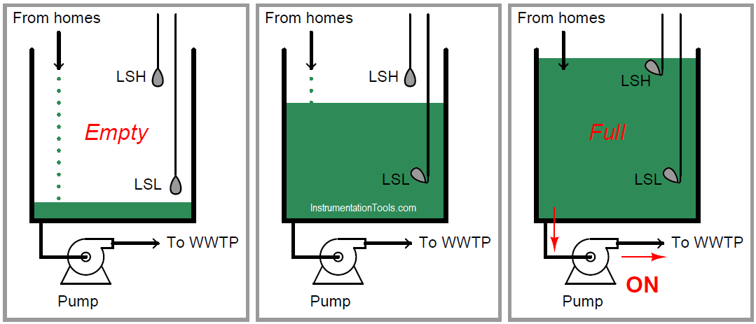
Pump Control using level switches

An electrician needs to perform some routine “megger” measurements on the electric pump motor. “Megger” is the brand name of a high-voltage ohmmeter used to check the integrity of electrical insulation in electric motors, transformers, and other devices with wire coils subject to faults due to corrosion, vibration, or overheating.

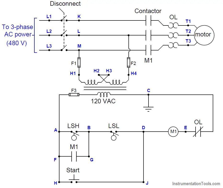
Here, the electrician will check resistance between each of the motor’s terminals (T1, T2, T3) and the metal frame of the motor, ensuring there are many millions of ohms (open) as the wire insulation should provide.

Troubleshooting Pump Control Circuit

Like all ohmmeter tests, a “megger” check must be performed on a device that is unpowered. For this reason, and also for personal safety, the electrician must ensure no power will get to the motor during his test.

Before commencing the test, the electrician follows this procedure to ensure the motor is in a zero energy state:

(1) Turn off the disconnect switch

(2) Place a padlock and a danger tag on the switch’s handle to ensure it cannot turn on

(3) Push the “Start” pushbutton switch to check that the pump does not start up

(4) Use an AC voltmeter to verify 0 volts between the following test points:

(a) Voltage between terminals K and L
(b) Voltage between terminals K and M
(c) Voltage between terminals L and M
(d) Voltage between terminals K and earth ground
(e) Voltage between terminals L and earth ground
(f) Voltage between terminals M and earth ground

(5) Use the same AC voltmeter to verify 480 volts between any two of the L1, L2, and L3 test points

Explain the rationale behind each step in this sequence. Although this many steps may appear to be a bit paranoid, there is actually logical justification for each one.

Solution:

Step 1 should ensure zero energy at the motor.

Step 2 alerts others not to re-energize the motor.

Step 3 is a check to see that the correct motor has been locked out.

Step 4 checks for voltage at all possible 2-point combinations on the power conductors.

Step 5 verifies that the voltmeter is properly functioning.

Suppose another electrician looked at this diagram and declared, “We don’t actually have to turn the disconnect switch off – we can prevent power from getting to the motor’s terminals just by just pulling any one of the fuses in this circuit!

If the M1 coil can’t energize with 120 volts, then the M1 contactor relay cannot close, which effectively locks out 480 volt power from getting to the motor.”

What would be your response to this electrician’s suggestion, and why?

Solution:

Pulling a fuse on a control circuit forces the motor contactor to be a safety device, which it was never intended to be.

Furthermore, it makes re-energizing the motor as simple as replacing a low-voltage fuse, which is far too easy (and therefore likely) for someone to do.

Questions for You:

  1. What sort of information do you think the electrician should write on the danger tag?
  2. Why do you suppose it is necessary to use high voltage to test the insulation integrity of an electric motor? Why not just use a regular ohmmeter that only uses a few volts between the test probes?
  3. Explain the operation of above pump control circuit?

Share your Answers with us through comments.

Credits: Tony R. Kuphaldt

Read Next:

  • PLC Star Delta Starter
  • Motor ON OFF Logic
  • Electric Motor Actuator
  • Diagnosing Motor Circuit
  • Electrical Wiring Terminology
Don't Miss Our Updates
Be the first to get exclusive content straight to your email.
We promise not to spam you. You can unsubscribe at any time.
Invalid email address
You've successfully subscribed !

Continue Reading

Instrument Loop Test Requirements and Operation Procedures
What is Advanced Process Control (APC)?
Design Document for Project Systems Architecture
Industrial Automation Pre-Engineering Design Documents – Project & Process
Loop-powered 4-20 mA Transmitter Circuit Voltage drop
Inspection and Testing of Fiber Optic Cable
Share This Article
Facebook Whatsapp Whatsapp LinkedIn Copy Link
Share
2 Comments
  • that1guy says:
    February 1, 2020 at 8:29 pm

    I appreciate these articles very much,
    I realize the idea behind leaving some Questions blanked with no Answers is designed to make you think,
    but it would be nice if you followed up in the future with your preferred answers for the questions you provide.
    That way the reader/learner can see what you believe to be a good perspective on the matter as well.

    Thank you,
    KEEP UP the good work guys – this site is great
    Long time reader

    Reply
  • M says:
    February 13, 2023 at 8:53 am

    I remember VFD motor’s cable leads sometimes stay a bit charged after power us disconnected. Ground them out when removing them or touching cable leads.

    Reply

Leave a Reply Cancel reply

Your email address will not be published. Required fields are marked *

Stay Connected

128.3kFollowersLike
69.1kFollowersFollow
210kSubscribersSubscribe
38kFollowersFollow

Categories

Explore More

Manufacturing Execution System (MES) in Industrial Automation
Distributed Control System Objective Questions
Feedforward Control with Dynamic Compensation
Remote Connectivity to Industrial Automation Systems
How a 4-20mA Transmitter Works?
Siemens PLC Course for Beginners: Problems and Solutions
Anti-static Wrist Straps in Industrial Automation
Self-regulating Processes – Liquid Flow Control

Keep Learning

What is a Network Switch?

Network Switch Requirement in SCADA and DCS Architecture

Difference between Router, Switch, and Hub

Difference between Router, Switch, and Hub

Zener Barrier Protection

Zener Diode Barrier Principle

PID Controller

Proportional Integral Derivative Controllers – PID MCQ

How is Data Stored in Standard Modbus Protocol?

How is Data Stored in Standard Modbus Protocol?

Cyber Security Multiple Choice Questions and Answers

Cyber Security Multiple Choice Questions and Answers

Limit, Selector, and Override controls

Limit, Selector, and Override controls

Overview of Industrial Control Systems

Overview of Industrial Control Systems

Learn More

Quiz on Electrical Meters and Measurement

200+ Quiz on Electrical Meters, Measurement, and Troubleshooting

Feedforward control with feedback trim

Feedforward Control Principle

Stability in Frequency Domain

Time Domain Analysis

Maintenance Override Switch (MOS)

What is Maintenance Override Switch (MOS) ?

Types of Angular Velocity Measurement

Types of Angular Velocity Measurement

Electrical Machines Questions and Answers

Speed Control of DC Motors Quiz

Baffle Nozzle Question

Baffle Nozzle Question

Series Air Fuel Combustion Control

Combustion Control – Series and Parallel Air-Fuel Ratio Control

Menu

  • About
  • Privacy Policy
  • Copyright

Quick Links

  • Learn PLC
  • Helping Hand
  • Part Time Job

YouTube Subscribe

Follow US
All rights reserved. Reproduction in whole or in part without written permission is prohibited.
Welcome Back!

Sign in to your account

Username or Email Address
Password

Lost your password?