Inst ToolsInst ToolsInst Tools
  • Ask
  • Courses
  • Videos
  • Q & A
    • Interview
      • Instrumentation
      • Electronics
      • Electrical
      • Practical Questions
    • MCQ
      • Instrumentation MCQ
      • Electrical MCQ
      • Electronics MCQ
      • Control Systems MCQ
      • Analog Electronics MCQ
      • Digital Electronics MCQ
      • Power Electronics MCQ
      • Microprocessor MCQ
      • Multiple Choice Questions
  • EE
    • Electronics
      • Electronics Q & A
      • Electronic Basics
      • Electronic Devices & Circuits
      • Electronics Animation
      • Digital Electronics
    • Electrical
      • Electrical Basics
      • Electrical Q & A
      • Power Electronics
      • Electrical Machines
      • Electrical Animation
      • Power Systems
      • Switchgear & Protection
      • Transmission & Distribution
  • Measure
    • Control Valves
    • Calibration
    • Temperature
    • Pressure
    • Flow
    • Level
    • Analyzers
    • Switches
    • Vibration
    • Solenoid Valve
  • Control
    • PLC Tutorials
    • Control Systems
    • Safety Instrumented System (SIS)
    • Communication
    • Fire & Gas System
  • More
    • Design
    • Tools
    • Animation
    • Basics
    • Formulas
    • Standards
    • TextBooks
    • Common
    • Software
    • Excel Tools
    • Erection & Commissioning
    • Process Fundamentals
    • Videos
    • Books
Search
All rights reserved. Reproduction in whole or in part without written permission is prohibited.
Reading: Troubleshooting Magnetic Flow Meters Common Problems
Share
Notification Show More
Font ResizerAa
Inst ToolsInst Tools
Font ResizerAa
  • Courses
  • PLC Tutorials
  • Control Systems
Search
  • Ask
  • Courses
  • Videos
  • Q & A
    • Interview
    • MCQ
  • EE
    • Electronics
    • Electrical
  • Measure
    • Control Valves
    • Calibration
    • Temperature
    • Pressure
    • Flow
    • Level
    • Analyzers
    • Switches
    • Vibration
    • Solenoid Valve
  • Control
    • PLC Tutorials
    • Control Systems
    • Safety Instrumented System (SIS)
    • Communication
    • Fire & Gas System
  • More
    • Design
    • Tools
    • Animation
    • Basics
    • Formulas
    • Standards
    • TextBooks
    • Common
    • Software
    • Excel Tools
    • Erection & Commissioning
    • Process Fundamentals
    • Videos
    • Books
Follow US
All rights reserved. Reproduction in whole or in part without written permission is prohibited.
Inst Tools > Blog > Flow Measurement > Troubleshooting Magnetic Flow Meters Common Problems

Troubleshooting Magnetic Flow Meters Common Problems

This article discusses the troubleshooting steps for a magnetic flow meter and their common problems with solutions.

Last updated: February 21, 2023 3:00 pm
Editorial Staff
Flow Measurement
2 Comments
Share
6 Min Read
SHARE

This article discusses the troubleshooting steps for a magnetic flow meter. The magnetic flow meter’s troubleshooting is a bit typical. This is because we rarely face issues with the magnetic flow meter.

But when we face an issue, the troubleshooting becomes very difficult because we are not doing frequent activities on the magnetic flow meter.

Troubleshooting Magnetic Flow Meters

Troubleshooting Magnetic Flow Meters Common Problems

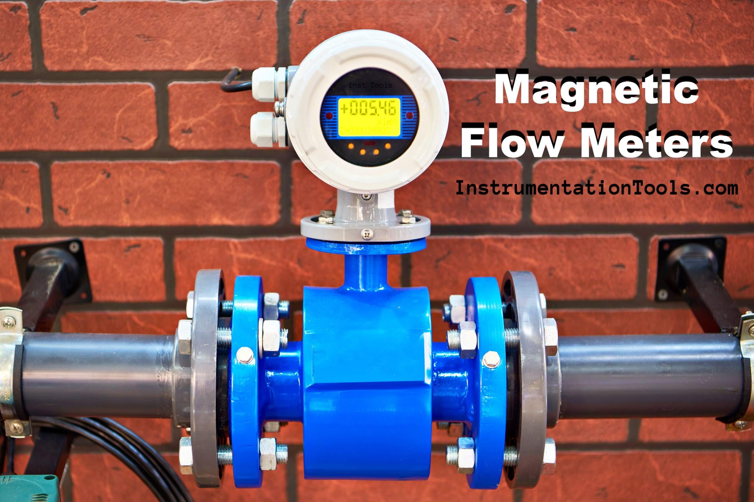
Below mentioned steps will help for troubleshooting a magnetic flow meter:

  1. Check whether the magnetic flow meter is in power ON condition or not. If magnetic flow meter is in power off condition, then check the voltage. If voltage is not present, then check the MCB in the marshalling cabinet. MCB might be in trip condition. If MCB is found in trip condition, then first check the field connections. The power connections for magnetic flow meter are in a separate compartment. Issue can be short circuit or water ingress in this compartment. (A fuse will also be present in the power loop of the magnetic flow meter. Check the fuse also).
  2. Check the sensor’s connections in the magnetic flow meter’s transmitter. A separate compartment other than power cable compartment is present for this. Verify the connections as per the vendor manual. Correct the connections if connections are having any issue. Also check the connections on the sensor head. The connections should be as per the vendor manual.
  3. If voltage is present but the flow meter is not powering up, then check the fuse which is available on the Printed Circuit Board (PCB) also. Check the healthiness of the fuse. Replace the power card if found faulty.
  4. Now check the cable healthiness which is connecting the magnetic flow meter’s transmitter and the sensor.
  5. If the magnetic flow meter’s transmitter is mounted directly on the sensor, then check the connections in the magnetic flow meter’s transmitter.
  6. Check the grounding in the magnetic flow meter’s transmitter as well as sensors. Follow guideline for properly grounding as per vendor manual.
  7. Check all the configuration data as per datasheet. Magnetic flow meter has many configuration data. Check the GK, GKL and f-field value in the configuration. For a specific magnetic flow meter, a transmitter and sensor pair are there. If we use a different transmitter with different sensor, then there will be problem in the value of the flow measured. The transmitter nameplate has GK, GKL and f-field value. Verify the serial number on the transmitter nameplate and the sensor nameplate. Both should be as per the datasheet provided by the vendor.
  8. If the flow is showing in negative values, then check the installation direction of the magnetic flow meter. The direction of installation might be incorrect. Change the flow direction from configuration or can change the sensor installation direction.
  9. Check the configured flow range in the field instrument as well as the control system. If range is incorrect on any side i.e. field or system side, then flow mismatch will be there. Correct the range if found incorrect.
  10. If flow measured by the magnetic flow meter is very high or very low then there might be off-specifications in terms of conductivity. The conductivity of the fluid can be too high or too low.
  11. Magnetic flow meter’s transmitter has cards like power card, communication card, signal conversion card, depending on the make and model number. So, check their physical condition after powering off the magnetic flow meter.
  12. If error on magnetic flow meter is Pipe Not Full, then there is actual low level in pipe. For this flow needs to be increased or the downstream valve to be closed by a few percentages. If the level in the pipe is ok, then there might be a deposition layer of external material on the sensor electrodes. For this dropping of the sensor is needed for cleaning the sensor’s electrodes.
  13. If error on magnetic flow meter is Empty Pipe, the liquid might not be present in the line or an external material’s layer deposition has occurred.
  14. The fluid flow should be without bubbles and solid particles. Ensure the same.
  15. After dropping magnetic flow meter’s sensor, clean the electrodes and inspect the condition of the electrodes. Check the continuity between the terminal block and the internal electrode. Resistance should be less than 1 ohm. This is because the electrodes are directly connected with connections on the terminal block.
  16. Check the resistance of the coil. The resistance should be as per the resistance mentioned in the vendor manual. If coil resistance is found too high, then the coil is damaged and if the coil resistance is too low, then there might be some kind of short circuit in the coil.
  17. Corrosion or damaged electrodes can also be creating the problems. Replace the sensor if the electrodes are damaged or corroded.
  18. Do not do any kind of calibration in the field. Ask vendor assistance for the calibration job.

Read Next:

  • Wiring of Solenoid and PLC
  • Orifice Plate Design Rules
  • Level Instruments Specification
  • Variable Area Flow Meter
  • All About Turbine Meter
Don't Miss Our Updates
Be the first to get exclusive content straight to your email.
We promise not to spam you. You can unsubscribe at any time.
Invalid email address
You've successfully subscribed !
Wedge Flow Meter Principle
DP type Flow Transmitter Preventive Maintenance and Calibration
Transit Time Flow Meter Principle
Flow Standards
Difference between Different Types of Flow Meters
Share This Article
Facebook Whatsapp Whatsapp LinkedIn Copy Link
Share
2 Comments
  • Syed Ahsan Raza says:
    June 22, 2023 at 1:47 pm

    What if my flow meter is still reading some value, while the line is empty.

    Reply
  • Marvin Randall says:
    October 3, 2023 at 3:06 am

    What would cause my IFM flow meter reading to become instable?

    Reply

Leave a Reply Cancel reply

Your email address will not be published. Required fields are marked *

Stay Connected

128.3kFollowersLike
69.1kFollowersFollow
208kSubscribersSubscribe
38kFollowersFollow

Categories

Recent Comments

  • Guifty Shimica on Top Non-PLC Certification Courses for Automation Professionals
  • Guifty Shimica on Top Non-PLC Certification Courses for Automation Professionals
  • MIHARITSOA Aina Sitraka on Top Non-PLC Certification Courses for Automation Professionals
  • Vaishnavi on Free Instrumentation Course for Trainee Engineers

Related Articles

Impeller Flow Sensor

Impeller Flow Sensor Working Principle and Animation

Coriolis flow meter sensor coils

Coriolis Flow Meter Construction

Interview on Flow Measurement

Interview Questions on Flow Measurement

W Type Transit Time Flow Meter

Transit Time Flow Meter – Types, Advantages, Disadvantages

vortex flow transmitter

What is a Vortex Flow Meter?

Step by step guide for Gas Flow Meter Calibration

Step by Step Guide for Gas Flow Meter Calibration

Pressure and Temperature Compensation for Flow Transmitter

Why Pressure & Temperature Compensation required for Orifice Flow Meters ?

Mass Flow Calculations of flow measurement

Mass Flow Calculations

More Articles

VFD Block Diagram

What is a VFD? – Theory, Advantages, Disadvantages

Pressure Transmitter

Pressure Transmitter Animation

Electronic Symbols List

Electronic Symbols

Clamp meters

Clamp Meters Working Principle

Closed Tank Level Measurement Formula

Siemens Differential Pressure Transmitter Calculations (Flange Type)

Calculate the Thermocouple Output millivolts

Calculate the Thermocouple Output millivolts

What is a Voltage Reference

What is a Voltage Reference? – Electronic Components

Why is IGBT used in VFD

Why is IGBT used in VFD?

Follow US
All rights reserved. Reproduction in whole or in part without written permission is prohibited.
Welcome Back!

Sign in to your account

Username or Email Address
Password

Lost your password?