Introduction
A fieldbus system is a distributed system composed of field devices and control and monitoring equipment integrated into the physical environment of a plant or factory. Fieldbus devices work together to provide I/O and control for automated processes and operations. The Fieldbus foundation provides a framework for describing these systems as a collection of physical devices interconnected by a fieldbus network. One of the ways the physical devices are used is to perform their portion of the total system operation by implementing one or more function blocks
Function Blocks
Function blocks within the fieldbus device perform the various functions required for process control. Because each system is different, the mix and configuration of functions are different. Therefore, the Fieldbus FOUNDATION has designed a range of function blocks, each addressing a different need.
Function blocks perform process control functions, such as analog input (AI) and analog output (AO) functions as well as proportional-integral-derivative (PID) functions. The standard function blocks provide a common structure for defining function block inputs, outputs, control parameters, events, alarms, and modes, and combining them into a process that can be implemented within a single device or over the fieldbus network. This simplifies the identification of characteristics that are common to function blocks.
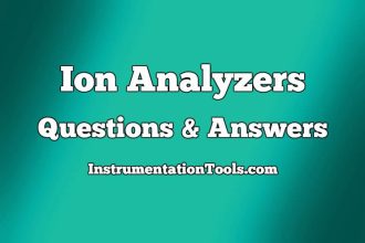
Figure 1-1 illustrates the internal structure of a function block. When execution begins, input parameter values from other blocks are snapped-in by the block. The input snap process ensures that these values do not change during the block execution. New values received for these parameters do not affect the snapped values and will not be used by the function block during the current execution.
 Once the inputs are snapped, the algorithm operates on them, generating outputs as it progresses. Algorithm executions are controlled through the setting of contained parameters. Contained parameters are internal to function blocks and do not appear as normal input and output parameters. However, they may be accessed and modified remotely, as specified by the function block.
Input events may affect the operation of the algorithm. An execution control function regulates the receipt of input events and the generation of output events during execution of the algorithm. Upon completion of the algorithm, the data internal to the block is saved for use in the next execution, and the output data is snapped, releasing it for use by other function blocks.
A block is a tagged logical processing unit. The tag is the name of the block. System management services locate a block by its tag. Thus the service personnel need only know the tag of the block to access or change the appropriate block parameters.
Function blocks are also capable of performing short-term data collection and storage for reviewing their behavior.
Device Descriptions
Device Descriptions are specified tool definitions that are associated with the function blocks. Device descriptions provide for the definition and description of the function blocks and their parameters.
To promote consistency of definition and understanding, descriptive information, such as data type and length, is maintained in the device description. Device Descriptions are written using an open language called the Device Description Language (DDL). Parameter transfers between function blocks can be easily verified because all parameters are described using the same language. Once written, the device description can be stored on an external medium, such as a CD-ROM or harddisk. Users can then read the device description from the external medium. The use of an open language in the device description permits interoperability of function blocks within devices from various vendors. Additionally, human interface devices, such as operator consoles and computers, do not have to be programmed specifically for each type of device on the bus. Instead their displays and interactions with devices are driven from the device descriptions.
Device descriptions may also include a set of processing routines called methods. Methods provide a procedure for accessing and manipulating parameters within a device.
BLOCK OPERATION
In addition to function blocks, fieldbus devices contain two other block types to support the function blocks. These are the resource block and the transducer block. The resource block contains the hardware specific characteristics associated with a device. Transducer blocks couple the function blocks to local input/output functions.
Instrument-Specific Function Blocks
Resource Blocks
Resource blocks contain the hardware specific characteristics associated with a device; they have no input or output parameters. The algorithm within a resource block monitors and controls the general operation of the physical device hardware. The execution of this algorithm is dependent on the characteristics of the physical device, as defined by the manufacturer. As a result of this activity, the algorithm may cause the generation of events. There is only one resource block defined for a device. For example, when the mode of a resource block is “out of service,” it impacts all of the other blocks.
Transducer Blocks
Transducer blocks connect function blocks to local input/output functions. They read sensor hardware and write to effector (actuator) hardware. This permits the transducer block to execute as frequently as necessary to obtain good data from sensors and ensure proper writes to the actuator without burdening the function blocks that use the data. The transducer block also isolates the function block from the vendor specific characteristics of the physical I/O.
Alerts
When an alert occurs, execution control sends an event notification and waits a specified period of time for an acknowledgment to be received. This occurs even if the condition that caused the alert no longer exists. If the acknowledgment is not received within the pre-specified time-out period, the event notification is retransmitted. This assures that alert messages are not lost.
Two types of alerts are defined for the block, events and alarms. Events are used to report a status change when a block leaves a particular state, such as when a parameter crosses a threshold. Alarms not only report a status change when a block leaves a particular state, but also report when it returns back to that state.
NETWORK COMMUNICATION
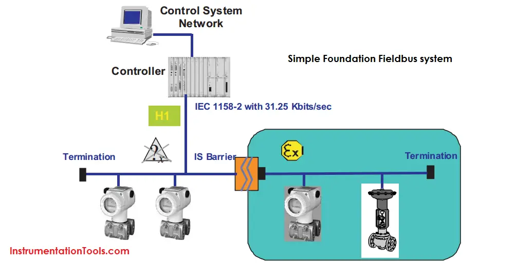
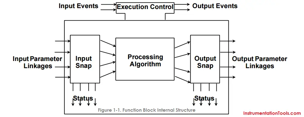
Figure 1-2 illustrates a simple fieldbus network consisting of a single segment (link).
Link Active Scheduler (LAS)
All links have one and only one Link Active Scheduler (LAS). The LAS operates as the bus arbiter for the link. The LAS does the following:
- recognizes and adds new devices to the link.
- removes non-responsive devices from the link.
- distributes Data Link (DL) and Link Scheduling (LS) time on the link. Data Link Time is a network-wide time periodically distributed by the LAS to synchronize all device clocks on the bus. Link Scheduling time is a link-specific time represented as an offset from Data Link Time. It is used to indicate when the LAS on each link begins and repeats its schedule. It is used by system management to synchronize function block execution with the data transfers scheduled by the LAS.
- polls devices for process loop data at scheduled transmission times.
- distributes a priority-driven token to devices between scheduled transmissions.
Any device on the link may become the LAS, as long as it is capable. The devices that are capable of becoming the LAS are called link master devices. All other devices are referred to as basic devices. When a segment first starts up, or upon failure of the existing LAS, the link master devices on the segment bid to become the LAS. The link master that wins the bid begins operating as the LAS immediately upon completion of the bidding process. Link masters that do not become the LAS act as basic devices. However, the link masters can act as LAS backups by monitoring the link for failure of the LAS and then bidding to become the LAS when a LAS failure is detected.
Only one device can communicate at a time. Permission to communicate on the bus is controlled by a centralized token passed between devices by the LAS. Only the device with the token can communicate. The LAS maintains a list of all devices that need access to the bus. This list is called the “Live List.”
Two types of tokens are used by the LAS. A time-critical token, compel data (CD), is sent by the LAS according to a schedule. A non-time critical token, pass token (PT), is sent by the LAS to each device in ascending numerical order according to address.
Device Addressing
Fieldbus uses addresses between 0 and 255. Addresses 0 through 15 are reserved for group addressing and for use by the data link layer. For all Fisher-Rosemount fieldbus devices addresses 20 through 35 are available to the device. If there are two or more devices with the same address, the first device to start will use its programmed address. Each of the other devices will be given one of four temporary addresses between 248 and 251. If a temporary address is not available, the device will be unavailable until a temporary address becomes available.
Scheduled Transfers
Information is transferred between devices over the fieldbus using three different types of reporting.
• Publisher/Subscriber: This type of reporting is used to transfer critical process loop data, such as the process variable. The data producers (publishers) post the data in a buffer that is transmitted to the subscriber (S), when the publisher receives the Compel data. The buffer contains only one copy of the data. New data completely overwrites previous data. Updates to published data are transferred simultaneously to all subscribers in a single broadcast. Transfers of this type can be scheduled on a precisely periodic basis.
• Report Distribution: This type of reporting is used to broadcast and multicast event and trend reports. The destination address may be predefined so that all reports are sent to the same address, or it may be provided separately with each report. Transfers of this type are queued. They are delivered to the receivers in the order transmitted, although there may be gaps due to corrupted transfers. These transfers are unscheduled and occur in between scheduled transfers at a given priority.
• Client/Server: This type of reporting is used for request/response exchanges between pairs of devices. Like Report Distribution reporting, the transfers are queued, unscheduled, and prioritized. Queued means the messages are sent and received in the order submitted for transmission, according to their priority, without overwriting previous messages. However, unlike Report Distribution, these transfers are flow controlled and employ a retransmission procedure to recover from corrupted transfers.
Scheduled Transfers
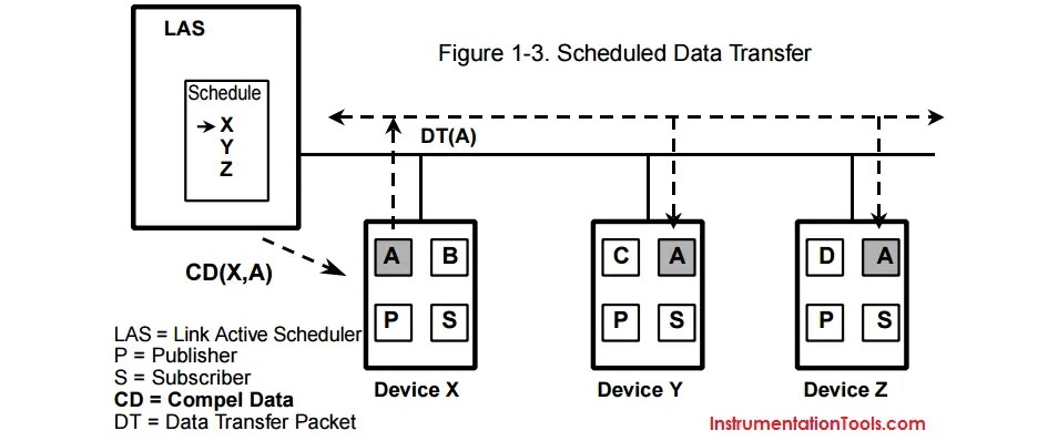
Figure 1-3 diagrams the method of scheduled data transfer. Scheduled data transfers are typically used for the regular cyclic transfer of process loop data between devices on the fieldbus. Scheduled transfers use publisher/subscriber type of reporting for data transfer. The Link Active Scheduler maintains a list of transmit times for all publishers in all devices that need to be cyclically transmitted. When it is time for a device to publish data, the LAS issues a Compel Data (CD) message to the device. Upon receipt of the CD, the device broadcasts or “publishes” the data to all devices on the fieldbus. Any device that is configured to receive the data is called a “subscriber.”
Unscheduled Transfers
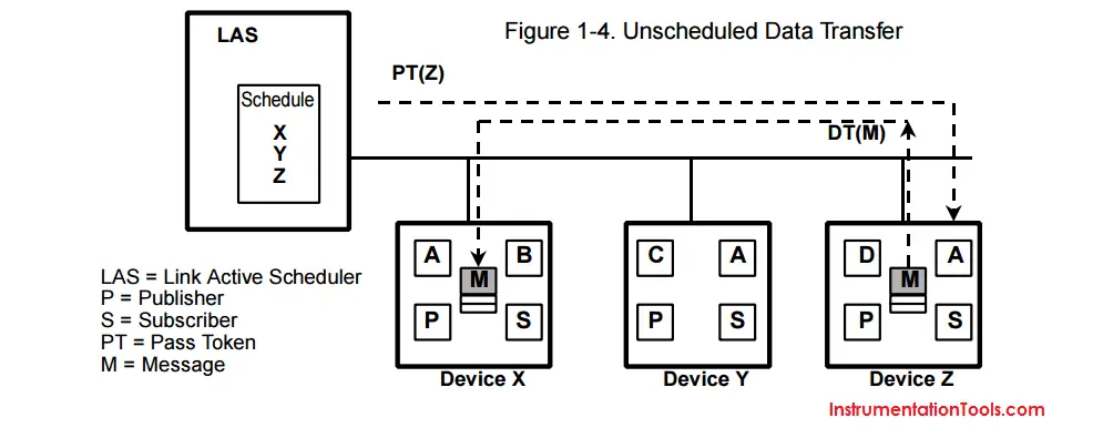
Figure 1-4 diagrams an unscheduled transfer. Unscheduled transfers are used for things like user-initiated changes, including set point changes, mode changes, tuning changes, and upload/download. Unscheduled transfers use either report distribution or client/server type of reporting for transferring data.
All of the devices on the fieldbus are given a chance to send unscheduled messages between transmissions of scheduled data. The LAS grants permission to a device to use the fieldbus by issuing a pass token (PT) message to the device. When the device receives the PT, it is allowed to send messages until it has finished or until the “maximum token hold time” has expired, whichever is the shorter time. The message may be sent to a single destination or to multiple destinations.
Function Block Scheduling
Figure 1-5 shows an example of a link schedule. A single iteration of the link-wide schedule is called the macrocycle. When the system is configured and the function blocks are linked, a master link-wide schedule is created for the LAS. Each device maintains its portion of the link-wide schedule, known as the Function Block Schedule. The Function Block Schedule indicates when the function blocks for the device are to be executed. The scheduled execution time for each function block is represented as an offset from the beginning of the macrocycle start time.
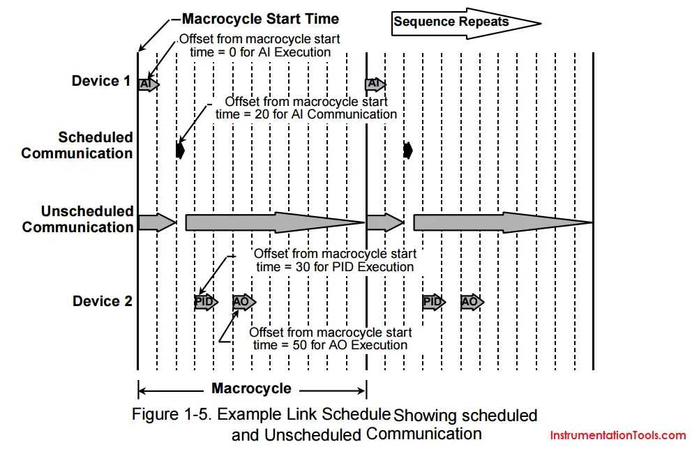
To support synchronization of schedules, periodically Link Scheduling (LS) time is distributed. The beginning of the macrocycle represents a common starting time for all Function Block schedules on a link and for the LAS link-wide schedule. This permits function block executions and their corresponding data transfers to be synchronized in time.
The Fieldbus main Function Blocks. click below for detailed information
- Analog Input Function Block
- Analog Output Function Block
- Resource Block
- Transducer Block
- PID Block etc..