Inst ToolsInst ToolsInst Tools
  • Courses
  • Automation
    • PLC
    • Control System
    • Safety System
    • Communication
    • Fire & Gas System
  • Instrumentation
    • Design
    • Pressure
    • Temperature
    • Flow
    • Level
    • Vibration
    • Analyzer
    • Control Valve
    • Switch
    • Calibration
    • Erection & Commissioning
  • Interview
    • Instrumentation
    • Electrical
    • Electronics
    • Practical
  • Q&A
    • Instrumentation
    • Control System
    • Electrical
    • Electronics
    • Analog Electronics
    • Digital Electronics
    • Power Electronics
    • Microprocessor
  • Request
Search
  • Books
  • Software
  • Projects
  • Process
  • Tools
  • Basics
  • Formula
  • Power Plant
  • Root Cause Analysis
  • Electrical Basics
  • Animation
  • Standards
  • 4-20 mA Course
  • Siemens PLC Course
Reading: Troubleshooting DP type Transmitter Common Problems
Share
Font ResizerAa
Inst ToolsInst Tools
Font ResizerAa
  • Courses
  • Design
  • PLC
  • Interview
  • Control System
Search
  • Courses
  • Automation
    • PLC
    • Control System
    • Safety System
    • Communication
    • Fire & Gas System
  • Instrumentation
    • Design
    • Pressure
    • Temperature
    • Flow
    • Level
    • Vibration
    • Analyzer
    • Control Valve
    • Switch
    • Calibration
    • Erection & Commissioning
  • Interview
    • Instrumentation
    • Electrical
    • Electronics
    • Practical
  • Q&A
    • Instrumentation
    • Control System
    • Electrical
    • Electronics
    • Analog Electronics
    • Digital Electronics
    • Power Electronics
    • Microprocessor
  • Request
Follow US
All rights reserved. Reproduction in whole or in part without written permission is prohibited.
Inst Tools > Blog > Flow Measurement > Troubleshooting DP type Transmitter Common Problems

Troubleshooting DP type Transmitter Common Problems

This article covers the troubleshooting guidelines if you are facing practical common problems with a DP type transmitter.

Last updated: February 21, 2023 3:01 pm
Editorial Staff
Flow Measurement
No Comments
Share
5 Min Read
SHARE

This article covers the troubleshooting guidelines if you are facing practical common problems with a DP type transmitter. The DP transmitter can be used as a differential pressure transmitter, flow transmitter, or even as a level transmitter.

DP Transmitter Common Problems

DP type Flow Transmitter Preventive Maintenance

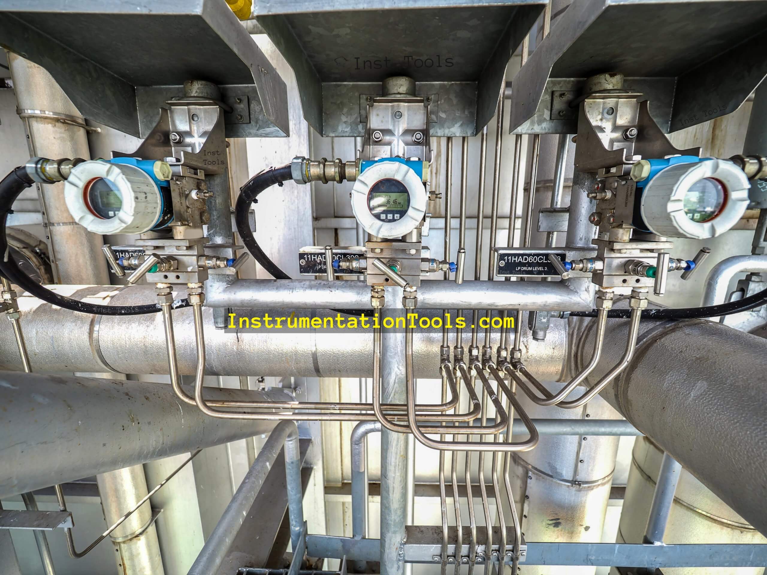
Let us see the troubleshooting guidelines for a DP-type transmitter.

Follow the below-mentioned steps:

  1. Check whether the DP-type transmitter is in power ON condition in the field or not. If the transmitter is in power-off condition, then check the cable connections. Trace the loop from the transmitter to the marshalling cabinet via the back tracing method.
  2. Check the barrier or isolator which is installed in the marshalling cabinet. If there is an issue with the barrier then replace it. If cable connections and barriers are found ok, then check the cable healthiness. Replace the cable pair with a spare cable if found unhealthy.
  3. If there is a reading mismatch between the field value and the PLC/DCS system, then verify the configured DP transmitter range in the field as well as in the system logic. Correct wherever found incorrect. Reference for the correct range should be taken from the transmitter datasheet or any other approved document.
  4. Check the impulse tube leakage for all tubing connections. If found leakage, then arrest the leak. Use a snoop liquid leak detector (or any other leak detector) for detecting the leakage.
  5. Now check the isolation valves which connect the transmitter to the process. If found in an isolated condition, then open the isolation valve. But before opening the isolation valve, verify the tube fittings and condition of the tube also.
  6. Check the condition of the manifold. The equalization valve should be in close condition. The isolation valves should be open and the vent valves should be in close condition. The vent plugs should be properly fixed.
  7. If the DP transmitter is wet leg type, then refill the wet leg with the appropriate fluid. Take necessary approvals for filling the wet leg.
  8. If one leg of DP type transmitter is at atmospheric reference, then check the condition of the leg. A bug arrester should be present on the leg at atmospheric reference.
  9. Check whether the transmitter leg open to the atmosphere is clear or not. The facing direction of the leg which is open to the atmosphere should be faced towards the ground. The Rainwater may go into the leg if it is facing towards the sky and it will disturb the measurement readings.
  10. If still the transmitter is not responding, then do flushing activity. Back-flushing in case of hazardous fluids and forward flushing in case of air and water is needed.
  11. For back flushing, pressurized fluid compatible with the process fluid will be needed. To develop pressure, a hand pump can be used. While using a hand pump, make sure to not-to increase the pressure above the impulse tube’s rated pressure. Flushing activity will remove the choked material inside the tubes and at the main tapping point.
  12. Verify whether the HP tapping of the transmitter is connected to the HP side of the primary pressure sensing element and the LP side is connected to the LP side of the pressure sensing element. If found incorrect, then correct by isolating the transmitter by using the isolation valves.
  13. After flushing, take the transmitter again in line and check the whole system again with a snoop solution or any other standard leak-detecting solution.
  14. Check the device configuration data such as LRV, URV, and mA range using a HART communicator. Use the transmitter datasheet for confirming the configured data.
  15. If still, the transmitter is not responding properly, check the response of the transmitter using a hand pump/Scandura depending upon the span range. 
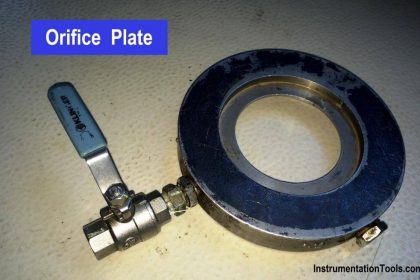
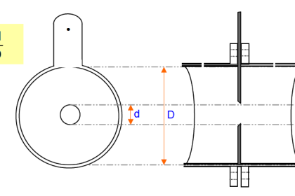
  16. Check the condition of the primary pressure sensing element i.e. orifice, venturi, pitot tube, or other primary sensing elements. For this purpose isolation of the line is necessary.
  17. Perform calibration of the DP type pressure transmitter using the calibrating device, the device’s response will be found ok.

Read Next:

  • Orifice Meter Specifications
  • Transmitter Calibration Frequency
  • Instrumentation and Control Quiz
  • Orifice Drain and Vent Hole
  • Facts about Orifice Plates
Don't Miss Our Updates
Be the first to get exclusive content straight to your email.
We promise not to spam you. You can unsubscribe at any time.
Invalid email address
You've successfully subscribed !

Continue Reading

Bernoulli’s Principle and Equation – Flow Measurement
What is Integral Flow Orifice Assembly?
Turbine Flow Meter Coefficient and Scaling Factor
What are Multiphase Flow Meters? – Working Principle, Advantages
Swirl Flow Meters Working Principle
Area Velocity Flow Meter Principle
Share This Article
Facebook Whatsapp Whatsapp LinkedIn Copy Link
Share
Leave a Comment

Leave a Reply Cancel reply

Your email address will not be published. Required fields are marked *

Stay Connected

128.3kFollowersLike
69.1kFollowersFollow
210kSubscribersSubscribe
38kFollowersFollow

Categories

Explore More

Importance of Flow Meter Turndown Ratio
Coriolis Mass Flow Meter Working Principle
Magnetic Flow Meter Animation
Different Types of Flow Elements
Difference between Transit time and Doppler Ultrasonic Flow Meter
Types of Vortex Flow Meter Sensors
What is a Square Root Extractor? – DP Flow Measurement
Prover Tank Calibration and Mass Flow Meter Verification Procedure

Keep Learning

Sick Flow meters

Flare Ultrasonic Flow Meter – SOPAS Engineering Tool

Coriolis mass flowmeter Density Measurement

How Coriolis Mass Flow Meter Measure Density?

Step by step guide for Gas Flow Meter Calibration

Step by Step Guide for Gas Flow Meter Calibration

Mass Flow Calculations of flow measurement

Mass Flow Calculations

Linear to Square Root Extraction

orifice-plate

Orifice Plate Turndown ratio

Location of Pressure Taps

Design Considerations of Orifice Plate

V Cone Flow Meter Working Principle

V Cone Flow Meter – Principle, Advantages, Disadvantages

Learn More

shape of the trim determines the valve characteristic

Control Valve Characteristics

Wiring Diagram

Wiring Diagram

Diode-vi-characteristic-curve-for-forward-bias

VI Characteristic of a Diode

Contacting Radar Tank Gauges

Radar Tank Gauging

Thermistors and Resistance Temperature Detectors (RTDs)

Thermistors and Resistance Temperature Detectors (RTDs)

Thermocouple Questions

Thermocouple Terminal block Questions

Laser Diode Working Principle

Laser Diode Working Principle

Select Right Type of Controller

How to Select the Right Type of Controller

Menu

  • About
  • Privacy Policy
  • Copyright

Quick Links

  • Learn PLC
  • Helping Hand
  • Part Time Job

YouTube Subscribe

Follow US
All rights reserved. Reproduction in whole or in part without written permission is prohibited.
Welcome Back!

Sign in to your account

Username or Email Address
Password

Lost your password?