Inst ToolsInst ToolsInst Tools
  • Courses
  • Automation
    • PLC
    • Control System
    • Safety System
    • Communication
    • Fire & Gas System
  • Instrumentation
    • Design
    • Pressure
    • Temperature
    • Flow
    • Level
    • Vibration
    • Analyzer
    • Control Valve
    • Switch
    • Calibration
    • Erection & Commissioning
  • Interview
    • Instrumentation
    • Electrical
    • Electronics
    • Practical
  • Q&A
    • Instrumentation
    • Control System
    • Electrical
    • Electronics
    • Analog Electronics
    • Digital Electronics
    • Power Electronics
    • Microprocessor
  • Request
Search
  • Books
  • Software
  • Projects
  • Process
  • Tools
  • Basics
  • Formula
  • Power Plant
  • Root Cause Analysis
  • Electrical Basics
  • Animation
  • Standards
  • 4-20 mA Course
  • Siemens PLC Course
Reading: Transmitter Detailed Specifications
Share
Font ResizerAa
Inst ToolsInst Tools
Font ResizerAa
  • Courses
  • Design
  • PLC
  • Interview
  • Control System
Search
  • Courses
  • Automation
    • PLC
    • Control System
    • Safety System
    • Communication
    • Fire & Gas System
  • Instrumentation
    • Design
    • Pressure
    • Temperature
    • Flow
    • Level
    • Vibration
    • Analyzer
    • Control Valve
    • Switch
    • Calibration
    • Erection & Commissioning
  • Interview
    • Instrumentation
    • Electrical
    • Electronics
    • Practical
  • Q&A
    • Instrumentation
    • Control System
    • Electrical
    • Electronics
    • Analog Electronics
    • Digital Electronics
    • Power Electronics
    • Microprocessor
  • Request
Follow US
All rights reserved. Reproduction in whole or in part without written permission is prohibited.
Inst Tools > Blog > Instrumentation Design > Transmitter Detailed Specifications

Transmitter Detailed Specifications

Last updated: March 28, 2022 11:19 am
Editorial Staff
Instrumentation Design
2 Comments
Share
4 Min Read
SHARE

Here we shall see detailed specifications of Transmitters used for Level, Pressure, Flow, DP applications.

Contents
Transmitter SpecificationsExample Specifications

Transmitter Specifications

Transmitter Detailed Specifications

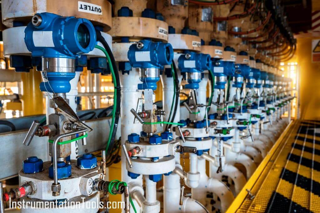
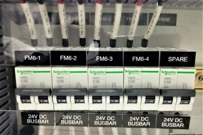
Transmitter used for flow, pressure, level, and DP applications are generally 2 wire 4-20 mA type depending on application and existing plan control system compatibility.

Sometimes foundation Fieldbus and Profibus protocols are also used for various applications.

Generally, transmitters should have the following features.

  • Transmitters should be SMART type
  • 2 wire 4-20 milliampere signal to be used
  • Should support HART protocol

Generally, transmitters shall be

  • Certified Ex-proof and for intrinsic safe applications Ex ia/ib rated
  • Die-cast Aluminium housing
  • Compatible with Direct mount or remote mounting accessories

Wetted part material normally is SS 316, as a minimum depending on process suitability. 125-150% of over-range protection is generally required.

Both coplanar and in-line transmitters are to be used for different applications.

External zero adjustment and internal vent/drain provision required.

Transmitter capable of measuring gauge / absolute pressure

The transmitter should be field configurable and should support multiple units of measurement.

Microprocessor-based control chip inside transmitter required with non-volatile memory to store configuration.

Signal conversion should be carried out in the transmitter itself and the design of the electronics should comply with Electromagnetic Compatibility requirements as per IEC 60801.

It should be capable of self-diagnosis and in event of failure, it should retain the fail safe value of output.

Built-in temperature sensors shall be provided for temperature compensation wherever required.

Instrument connection on Transmitter should generally be ½” NPT.

Various types of certifications should be available to choose from depending on the region it is to be used for example the USA or Europe.

Transmitter accuracy should be +/- 0.1% minimum but it is not possible for every case for example orifice meters do not provide that much accuracy because of the complexity of the measurement mechanism but the transmitter selected should have min +/- 0.1% accuracy.

Normally transmitter is calibrated in a way that it should read process LRV at about 25% of its measurement span and it should read URV at about 80%.

The transmitter should have internal transient protection inbuilt.

The transmitter shall support the latest version of the HART protocol. It shall also support multiple alarm level signal transmission. Typically these signals are superimposed over a 4-20 mA signal.

Transmitters for anti-surge control loops are non-smart type and flameproof unless specified otherwise.

A special smooth surface finish is required for sanitary services.

Generally, process connection for pressure and differential pressure transmitter shall be ½” NPTF and flanged for diaphragm seal type. Diaphragm seal element is used for corrosive and highly viscous services at high operating temperatures.

Capillary material SS 316 as a minimum, shall have SS 304 armoring with PVC cover, and for minimum measurement lag, proper ID should be selected.

Transmitter shall be installed with 2/3/5 valve manifold wherever it needs frequent removing of the transmitter for maintenance purposes.

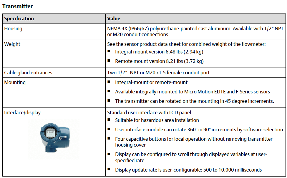
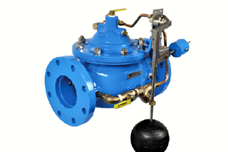
Here a snapshot from the brochure of one of the vendors of Transmitters is given for reference.

Example Specifications

Transmitter Specifications

Interest to add any further points? Share with us through below comments section.

Author: Kalpit Patel

Read Next:

  • Flowmeter Control Strategy
  • What is Averaging Pitot Tube?
  • Basics of Venturi Flow Meter
  • Differential Pressure Flowmeter
  • Flow Transmitter Square-Root
Don't Miss Our Updates
Be the first to get exclusive content straight to your email.
We promise not to spam you. You can unsubscribe at any time.
Invalid email address
You've successfully subscribed !

Continue Reading

Draw a ladder logic circuit for the electric motor of an air compressor ?
Turbine-Compressor System Architecture
Compliance Table Application (for Procurement Service Cycle)
Air Cylinder Consumption Calculation for Control Valves
Readings Mismatch between Field & Control Room ? Why
Response Time Test of RTD and Thermocouple
Share This Article
Facebook Whatsapp Whatsapp LinkedIn Copy Link
Share
2 Comments
  • Isaac Nyame says:
    June 28, 2020 at 10:07 pm

    Interesting, you people are doing very well

    Reply
    • Mr. Shah says:
      June 10, 2024 at 12:51 pm

      Thank you

      Reply

Leave a Reply Cancel reply

Your email address will not be published. Required fields are marked *

Stay Connected

128.3kFollowersLike
69.1kFollowersFollow
210kSubscribersSubscribe
38kFollowersFollow

Categories

Explore More

Process Control & Safety Systems Logics Implementing Cycle
Instrumentation and Process Teams Interactions in Design Engineering Companies
Pressure Control Valves vs Pressure Regulators
What’s the problem with shock and vibration ?
How to Select a Pneumatic Manifold
What is Instrument Heated Enclosure or Protection Box?
How-to Create Instrument Loop Diagram (ILD)?
15 Loop Diagram Questions

Keep Learning

How to Solve Cable Tray Sagging

How to Solve Cable Tray Sagging ?

Cable screen shall not be grounded

Cable Screen shall not be Grounded at Field Device ?

Switch or Transmitter

Switch or Transmitter

Design & Construction of Process Plant

Process Control Systems Philosophy Concept

Instrumentation Engineer in Process Plant Project

Instrumentation Engineer in Process Plant Project

Flow Control Valves

Difference Between a Flow Control & a Needle Valve

ISA and SAMA diagrams

What is SAMA Diagram?

IS Loop Formula

Difference between Intrinsic Safe and Non-Intrinsic Safe Cables

Learn More

Formulas to calculate ma from PV

Formulas to calculate mA from PV, LRV and URV

Thermal Mass Flowmeter Principle

Thermal Mass Flow Meter – Principle, Advantages, Applications

Two pressure transmitters

Pressure Transmitters Leg Compensation Technique

PLC Program for Star Delta Starter using Functional Block Diagram

PLC Program for Star Delta Starter using Functional Block Diagram

How to do Control Valve Sizing

How do you do control valve sizing in Layman’s terms?

Chromatography Questions & Answers

Gas Solid Chromatography Questions & Answers

Servo Operated Manometer Objective Questions

Servo Operated Manometer Objective Questions

Deluge System for Transformer Protection

Deluge System for Transformer Protection Animation

Menu

  • About
  • Privacy Policy
  • Copyright

Quick Links

  • Learn PLC
  • Helping Hand
  • Part Time Job

YouTube Subscribe

Follow US
All rights reserved. Reproduction in whole or in part without written permission is prohibited.
Welcome Back!

Sign in to your account

Username or Email Address
Password

Lost your password?