Inst ToolsInst ToolsInst Tools
  • Courses
  • Automation
    • PLC
    • Control System
    • Safety System
    • Communication
    • Fire & Gas System
  • Instrumentation
    • Design
    • Pressure
    • Temperature
    • Flow
    • Level
    • Vibration
    • Analyzer
    • Control Valve
    • Switch
    • Calibration
    • Erection & Commissioning
  • Interview
    • Instrumentation
    • Electrical
    • Electronics
    • Practical
  • Q&A
    • Instrumentation
    • Control System
    • Electrical
    • Electronics
    • Analog Electronics
    • Digital Electronics
    • Power Electronics
    • Microprocessor
Search
  • Books
  • Software
  • Projects
  • Process
  • Tools
  • Basics
  • Formula
  • Power Plant
  • Root Cause Analysis
  • Electrical Basics
  • Animation
  • Standards
  • 4-20 mA Course
  • Siemens PLC Course
Reading: Transmitter Minimum Span, Accuracy & Turndown
Share
Notification Show More
Font ResizerAa
Inst ToolsInst Tools
Font ResizerAa
  • Courses
  • Design
  • PLC
  • Interview
  • Control System
Search
  • Courses
  • Automation
    • PLC
    • Control System
    • Safety System
    • Communication
    • Fire & Gas System
  • Instrumentation
    • Design
    • Pressure
    • Temperature
    • Flow
    • Level
    • Vibration
    • Analyzer
    • Control Valve
    • Switch
    • Calibration
    • Erection & Commissioning
  • Interview
    • Instrumentation
    • Electrical
    • Electronics
    • Practical
  • Q&A
    • Instrumentation
    • Control System
    • Electrical
    • Electronics
    • Analog Electronics
    • Digital Electronics
    • Power Electronics
    • Microprocessor
Follow US
All rights reserved. Reproduction in whole or in part without written permission is prohibited.
Inst Tools > Blog > Instrumentation Design > Transmitter Minimum Span, Accuracy & Turndown

Transmitter Minimum Span, Accuracy & Turndown

Last updated: December 2, 2019 10:09 pm
Editorial Staff
Instrumentation Design
3 Comments
Share
6 Min Read
SHARE

Relation between Minimum span, accuracy & Turndown in Transmitters with a practical example

Before explaining minimum span & Turndown, lets start by an example highlighting Maximum span of sensor.

Suppose we want to measure pressure of 0-20 in H2O

Contents
Relation between Minimum span, accuracy & Turndown in Transmitters with a practical exampleMinimum Span :-Turndown :-Accuracy :-

So Rosemount 3051 offers 0 to 5 range options

If you look at range 0 (below screen shot) the Upper URL (Maximum Span) it can measure is 3 in H2O but we require 0-20 in H2O so the sensor selected is under-ranged
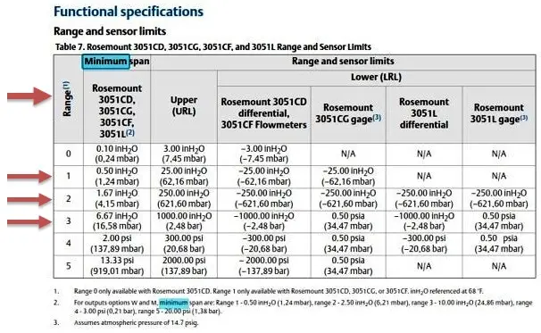
Transmitter Range and Sensor Limits

Image courtesy : Rosemount

So if we move ahead we have a range of 0 – 25 in H2O which fits our desired range (0 – 20 in H2O)

So we can select range 1 .

Simple right !!

Now lets look at minimum span

Minimum Span :-

CASE 1 :- Now imagine you have range 2 transmitter in your plant but range 1 transmitter is not present !!!!

And the pressure from management to install pressure transmitter (for 0 – 20 inH2O) is increasing so what would you do ???

Yes , guessed it right , take a leave and stay at home ….kidding !!! Open the catalog and refer to the page that talks about “range and sensor limits” (See Above Picture)

And “CHECK MINIMUM SPAN”

As we can see in the screen shot for “Range 2” we see minimum span is 1.67 inH2O i.e the Transmitter can be calibrated least up to 0 – 1.67 inH2O

Also ,Sometimes there is confusion ,”minimum span” that is 1.67 in H2O for range 2 means transmitter will not measure 1 inH2O , no that is not the case .transmitter will measure 1 inH2O

IN SIMPLE WORDS

For 0 inH2O transmitter will give 4mA

And for 1.67 inH2O transmitter will give 20mA

But the Transmitter with range 2 cannot give out 20mA for 1 inH2O !!!!!!!!!!

Even though the transmitter will measure 1 inH2O and provide a mA Signal (less than 20 mA)

So , yes for the above asked question range 2 will also work to measure 0 – 20 inH2O !!!!

The output will be as follows

0 inH20 = 4 mA

20 inH2O = 20 mA 

Lets be greedy !!! will range 3 also work for this Range ????

yes as the minimum span is 6.67 inH2O and this is greater than 0 – 20 inH2O

SO THEN IF SO MANY SENSOR RANGES CAN FIT WHY BOTHER SELECTING RANGE 1 ????????

The reason is the Turndown and accuracy are related to each other

Turndown :-

What we are doing in the above cases in Range 1 ,2 or 3 is “turning down” the transmitter max range to our desired range.

Turndown = Maximum span (URL) / Minimum (calibratable) span

So for case with range 1 (0 – 25 inH2O) and our desired range is 0 – 20 inH20

Lets calculate HOW MUCH WE ARE TURNING DOWN

The Turndown for our case is =25 inH2O / 20 inH2O

Turndown = 1.25

So here we are turning down 1.25 times

But for Range 3 (0- 1 000 inH2O)

Lets calculate HOW MUCH WE ARE TURNING DOWN

The Turndown for our case is =1000 inH2O / 20 inH2O

Turndown = 50

Here we are turning down 50 times as compared to 1.25 times for Range 1

Typical transmitters available in market have very high Turndown 100:1 but remember that If you turndown more the accuracy will get hampered !!

Practical example for our above case

Accuracy :-

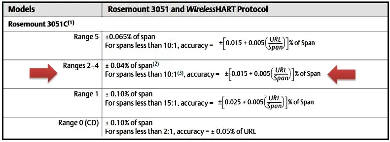
Below is screenshot that is taken from catalog that states for certain amount of turndown what will be the accuracy.

Transmitter Accuracy and Turndown

Image courtesy : Rosemount

If we select range 3 (0 – 1000 inH2O)

It is mentioned for turndown greater that 10:1 we need to use the formula provided to calculate Accuracy

LETS DO THAT !!!

={0.015+0.005(1000/20)} % of span

=0.265% inaccuracy

So the inaccuracy 0.04% changed to 0.265% if we use range 3 in our application of 0-20 inH2O

Note:-

This information is from Rosemount catalog is used for Example (as of March 2018)!

Rosemount may change and update the information , please refer latest catalog.

If any corrections I would be glad to know !!

Thanks for reading , hope this was helpful !!

Author : Asad Shaikh

Profile : Linkedin

Articles You May Like :

PLC Analog Signals Wiring

DP Transmitter for Level

Loop Supply Questions

DP Transmitter Error Calculation

Industrial Instrumentation MCQ
Don't Miss Our Updates
Be the first to get exclusive content straight to your email.
We promise not to spam you. You can unsubscribe at any time.
Invalid email address
You've successfully subscribed !

Continue Reading

Motor Protection Circuits
What is a Mimic Panel ?
Single and Three Phase Immersion Electrical Heaters Wiring Circuits
How to choose between PLC and DCS Systems ?
Types of Cables, Purpose, Advantages, Disadvantages, Applications
Control Valve Packing
Share This Article
Facebook Whatsapp Whatsapp LinkedIn Copy Link
Share
3 Comments
  • ASHISH KUMAR ROY says:
    August 1, 2019 at 10:44 am

    FRUITFUL,FANTASTIC.

    Reply
  • Hussain says:
    February 12, 2021 at 10:45 pm

    Thanks Asad. Very clear explanation and to the point.

    Reply
  • sergi says:
    December 26, 2022 at 3:06 pm

    What is meant by %accuracy of “SPAN”? What is this “span”? is this span 1000 inH2O or 20 inH20.

    So if the calculation results 0.1% of “SPAN”, does it mean 0.1% of 20 inH2O or 0.1% of 1000 inH2O? (in case of range 3)

    Reply

Leave a Reply Cancel reply

Your email address will not be published. Required fields are marked *

Stay Connected

128.3kFollowersLike
69.1kFollowersFollow
210kSubscribersSubscribe
38kFollowersFollow

Categories

Explore More

UPS Selection Factors for a Control System
All About Turbine Meters
Why 4-20 mA Standard is so popular ?
How O-Ring Failure caused NASA’s shuttle to Blast ?
How to Select the Right Panel Enclosure for Your Application?
Technical Specification for Uninterrupted Power Supply (UPS) System
Is Vacuum affects Field Instruments in Industries?
Solenoid Valve Selection Criteria

Keep Learning

Control Valve Recommended Practices

Control Valve Recommended Practices for Harsh Process Conditions

Pneumatic Valves and Cylinders Sizing

Pneumatic Valves and Cylinders Sizing – Part 2

How to Select a Inductive Proximity Sensor

How to Select a Inductive Proximity Sensor

General Specification of Thermowell

General Specification of Thermowell

Motor Primary Resistance Starter

Electrical Motor Starter Circuits

on off valve actuator

How to Select an Actuator for Valve

Top 10 Facts about HART Technology

Top 10 Facts about HART Technology

Pre-Engineering Design Documents

Industrial Automation Pre-Engineering Design Documents – Project & Process

Learn More

RTD Connection Diagram

Difference Between 2 wire RTD, 3 wire RTD, and 4 wire RTD’s

How a Multi Color LED Works

How a Multi Color LED Works ?

HT Motor Direction of Rotation (DOR)

HT Motor Direction of Rotation (DOR) Changed

Site Commissioning Steps for PLC Programmers

Site Commissioning Steps for PLC Programmers

Good and Bad Wiring Practices

Digital Logic Gates TruthTables

Logic Gates

Instrumentation Basics - Range Conversion Formula and Examples

Instrumentation Basics – Range Conversion Formula and Examples

C programming language

What is C Programming Language? Fundamentals, Pros & Cons

Menu

  • About
  • Privacy Policy
  • Copyright

Quick Links

  • Learn PLC
  • Helping Hand
  • Part Time Job

YouTube Subscribe

Follow US
All rights reserved. Reproduction in whole or in part without written permission is prohibited.
Welcome Back!

Sign in to your account

Username or Email Address
Password

Lost your password?