Inst ToolsInst ToolsInst Tools
  • Courses
  • Automation
    • PLC
    • Control System
    • Safety System
    • Communication
    • Fire & Gas System
  • Instrumentation
    • Design
    • Pressure
    • Temperature
    • Flow
    • Level
    • Vibration
    • Analyzer
    • Control Valve
    • Switch
    • Calibration
    • Erection & Commissioning
  • Interview
    • Instrumentation
    • Electrical
    • Electronics
    • Practical
  • Q&A
    • Instrumentation
    • Control System
    • Electrical
    • Electronics
    • Analog Electronics
    • Digital Electronics
    • Power Electronics
    • Microprocessor
  • Request
Search
  • Books
  • Software
  • Projects
  • Process
  • Tools
  • Basics
  • Formula
  • Power Plant
  • Root Cause Analysis
  • Electrical Basics
  • Animation
  • Standards
  • 4-20 mA Course
  • Siemens PLC Course
Reading: Transformer Operation Under No-Load
Share
Font ResizerAa
Inst ToolsInst Tools
Font ResizerAa
  • Courses
  • Design
  • PLC
  • Interview
  • Control System
Search
  • Courses
  • Automation
    • PLC
    • Control System
    • Safety System
    • Communication
    • Fire & Gas System
  • Instrumentation
    • Design
    • Pressure
    • Temperature
    • Flow
    • Level
    • Vibration
    • Analyzer
    • Control Valve
    • Switch
    • Calibration
    • Erection & Commissioning
  • Interview
    • Instrumentation
    • Electrical
    • Electronics
    • Practical
  • Q&A
    • Instrumentation
    • Control System
    • Electrical
    • Electronics
    • Analog Electronics
    • Digital Electronics
    • Power Electronics
    • Microprocessor
  • Request
Follow US
All rights reserved. Reproduction in whole or in part without written permission is prohibited.
Inst Tools > Blog > Electrical Theory > Transformer Operation Under No-Load

Transformer Operation Under No-Load

Last updated: August 7, 2018 3:09 pm
Editorial Staff
Electrical Theory
No Comments
Share
2 Min Read
SHARE

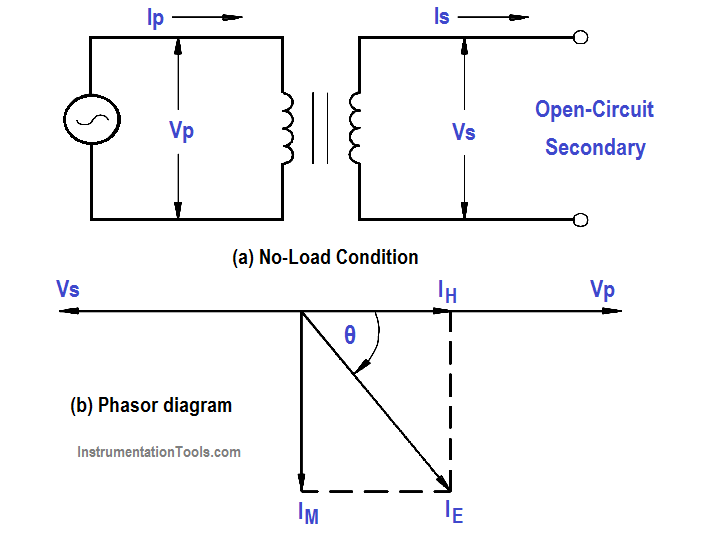
If the secondary of a transformer is left open-circuited (Figure 6), primary current is very low and is called the no-load current. No-load current produces the magnetic flux and supplies the hysteresis and eddy current losses in the core.

The no-load current (IE) consists of two components: the magnetizing current (Im ) and the core loss (IH). Magnetizing current lags applied voltage by 90°, while core loss is in phase with the applied voltage (Figure 1b). VP and VS are shown 180° out of phase. IH is very small in comparison with Im , and Im is nearly equal to IE . No-load current, IE , is also referred to as exciting current.

Transformer Operation Under No-Load

Figure 1 : Open-Circuit Secondary

Example:

When the secondary of a 120/440 V transformer is open, primary current is 0.2 amps at a PF of .3. The transformer is a 5 kVA transformer. Find: (a) IP ,  (b) IE   (c) IH , and (d) Im

Solution :

(a) Full Load Current = KVA Rating / Vp

(b) IP at no load current is equal to IE

(c) IH = IE Cos θ = IE  x PF

IH = 0.2 x 0.3 = 0.06 amps

(d) Im = IE Sin θ

θ = across 0.3 = 72.5°

Im = 0.19 amps
Don't Miss Our Updates
Be the first to get exclusive content straight to your email.
We promise not to spam you. You can unsubscribe at any time.
Invalid email address
You've successfully subscribed !

Continue Reading

Electro-Dynamo Meter Movement
Power Factor
Compound Generators
Moving Iron Vane Meter Movement
Capacitive Time Constant
Applying Kirchhoff’s Voltage Law
Share This Article
Facebook Whatsapp Whatsapp LinkedIn Copy Link
Share
Leave a Comment

Leave a Reply Cancel reply

Your email address will not be published. Required fields are marked *

Stay Connected

128.3kFollowersLike
69.1kFollowersFollow
210kSubscribersSubscribe
38kFollowersFollow

Categories

Explore More

Rectifiers, Forward Bias and Reverse Bias
Shunt-Wound Motor Operation
Types of AC Generators
AC Generator Voltage Regulators
Kirchhoff’s Laws
Transformer Voltage Ratio
Discharge and Charging of Lead-Acid Battery
Series Resistance

Keep Learning

Transformer Efficiency and Loses Formula

Transformer Losses and Efficiency

Calculate Power in Series RC Circuit

Calculate Power in Series RC Circuit

Capacitors Connected in Parallel

Series and Parallel Capacitors

Basic AC Generator

AC Generator Parts

Ground Detector Lamp Method Principle

Ground Detector Principle

Air Circuit Breaker Principle

High Voltage Circuit Breaker Principle

Marking Polarity

DC Circuit Analysis Loop Equations

Types of Fuses

Electrical System Components and Protection Devices

Learn More

Flange Types and Definitions

Flange Types and Definitions

Communication between Intouch Scada and Allen Bradley PLC

Communication between InTouch Scada and Allen Bradley PLC

Flapper nozzle system

Flapper Nozzle Questions

DC Motor Applications in Industries

Negative Readings in Gas Detectors

Why Negative Readings in Gas Detectors ?

DPDT switch

Switch Types and Common Terminology

Switches, Repeaters, Bridges, Routers, Firewalls

Switches, Repeaters, Bridges, Routers, Firewalls

Calculate DPT Calibrated Range

Calculate the Transmitter Values

Menu

  • About
  • Privacy Policy
  • Copyright

Quick Links

  • Learn PLC
  • Helping Hand
  • Part Time Job

YouTube Subscribe

Follow US
All rights reserved. Reproduction in whole or in part without written permission is prohibited.
Welcome Back!

Sign in to your account

Username or Email Address
Password

Lost your password?