Inst ToolsInst ToolsInst Tools
  • Courses
  • Automation
    • PLC
    • Control System
    • Safety System
    • Communication
    • Fire & Gas System
  • Instrumentation
    • Design
    • Pressure
    • Temperature
    • Flow
    • Level
    • Vibration
    • Analyzer
    • Control Valve
    • Switch
    • Calibration
    • Erection & Commissioning
  • Interview
    • Instrumentation
    • Electrical
    • Electronics
    • Practical
  • Q&A
    • Instrumentation
    • Control System
    • Electrical
    • Electronics
    • Analog Electronics
    • Digital Electronics
    • Power Electronics
    • Microprocessor
  • Request
Search
  • Books
  • Software
  • Projects
  • Process
  • Tools
  • Basics
  • Formula
  • Power Plant
  • Root Cause Analysis
  • Electrical Basics
  • Animation
  • Standards
  • 4-20 mA Course
  • Siemens PLC Course
Reading: Three Phase Wattmeter
Share
Notification Show More
Font ResizerAa
Inst ToolsInst Tools
Font ResizerAa
  • Courses
  • Design
  • PLC
  • Interview
  • Control System
Search
  • Courses
  • Automation
    • PLC
    • Control System
    • Safety System
    • Communication
    • Fire & Gas System
  • Instrumentation
    • Design
    • Pressure
    • Temperature
    • Flow
    • Level
    • Vibration
    • Analyzer
    • Control Valve
    • Switch
    • Calibration
    • Erection & Commissioning
  • Interview
    • Instrumentation
    • Electrical
    • Electronics
    • Practical
  • Q&A
    • Instrumentation
    • Control System
    • Electrical
    • Electronics
    • Analog Electronics
    • Digital Electronics
    • Power Electronics
    • Microprocessor
  • Request
Follow US
All rights reserved. Reproduction in whole or in part without written permission is prohibited.
Inst Tools > Blog > Electrical Theory > Three Phase Wattmeter

Three Phase Wattmeter

Last updated: August 13, 2018 11:19 am
Editorial Staff
Electrical Theory
No Comments
Share
1 Min Read
SHARE

Total power in a 3φ circuit is the sum of the powers of the separate phases. The total power could be measured by placing a wattmeter in each phase (below Figure); however, this method is not feasible since it is often impossible to break into the phases of a delta load. It also may not be feasible for the Y load, since the neutral point to which the wattmeters must be connected is not always accessible.

Three Phase Wattmeter principle

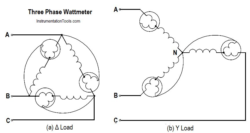
Figure : Wattmeters in Each Phase

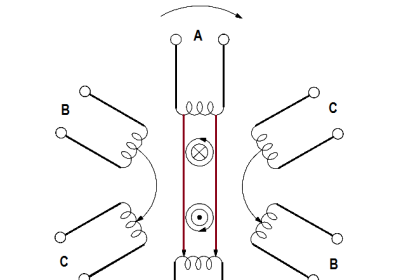
Normally, only two wattmeters are used in making 3φ power measurements (below Figure).

In balanced 3φ systems, with any power factor, total power is calculated by adding the A and B phase powers. The below Equation is the mathematical representation for calculating total power (PT).

PT = WA + WB

where WA and WB are the power readings in Phase A and Phase B.

Two Wattmeters to Measure 3 Phase Power

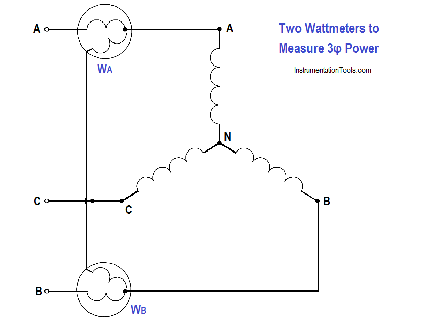
Figure : Two Wattmeters to Measure 3φ Power

Don't Miss Our Updates
Be the first to get exclusive content straight to your email.
We promise not to spam you. You can unsubscribe at any time.
Invalid email address
You've successfully subscribed !

Continue Reading

What is Electricity ?
Applying Kirchhoff’s Voltage Law
Series-Wound DC Generators
Wiring Diagram
4-Wire, Three-Phase Wye Wiring System
Battery Terminology
Share This Article
Facebook Whatsapp Whatsapp LinkedIn Copy Link
Share
Leave a Comment

Leave a Reply Cancel reply

Your email address will not be published. Required fields are marked *

Stay Connected

128.3kFollowersLike
69.1kFollowersFollow
210kSubscribersSubscribe
38kFollowersFollow

Categories

Explore More

Applying Kirchhoff’s Current Law
Power Triangle
DC Machines Terminology
AC Induction Motor Slip
Electrical Diagrams and Schematics
Types of AC Generators
Shunt-Wound DC Generators
Simplified Formulas for Parallel Circuit Resistance Calculations

Keep Learning

Wattmeter Principle

Wattmeter

Parallel Circuit

Parallel Circuit

Measuring Circuit Voltage

Voltmeters

Generator Action in a Motor

Generator Action in a Motor

Simple RL Circuit

Impedance in RL Circuits

Starting a Synchronous Motor

Starting a Synchronous Motor

Power Factor Meter Principle

Power Factor Meter Principle

relationship between resistance, reactance, and impedance

Impedance

Learn More

Electro Mechanical Systems Objective Questions

Electro Mechanical Systems Objective Questions

Ion Spectrometers Questions & Answers

Ion Spectroscopy Questions & Answers

100+ Quiz on Electrical Circuits and Control

100+ Quiz on Electrical Circuits and Control

Jog button in Motor Start Stop Logic using PLC

What is Motor Jogging ?

Peak Inverse Voltage of Center Tap Rectifier

Peak Inverse Voltage of Center Tap Rectifier

Globe Valve Parts

What is Globe Valve ?

What is Partial Stroke Test

What is Partial Stroke Test?

port-guided globe valve plug

What is Port-guided Globe Valve ?

Menu

  • About
  • Privacy Policy
  • Copyright

Quick Links

  • Learn PLC
  • Helping Hand
  • Part Time Job

YouTube Subscribe

Follow US
All rights reserved. Reproduction in whole or in part without written permission is prohibited.
Welcome Back!

Sign in to your account

Username or Email Address
Password

Lost your password?