Inst ToolsInst ToolsInst Tools
  • Courses
  • Videos
  • Q & A
    • Interview
      • Instrumentation
      • Electronics
      • Electrical
      • Practical Questions
    • MCQ
      • Instrumentation MCQ
      • Electrical MCQ
      • Electronics MCQ
      • Control Systems MCQ
      • Analog Electronics MCQ
      • Digital Electronics MCQ
      • Power Electronics MCQ
      • Microprocessor MCQ
      • Multiple Choice Questions
  • EE
    • Electronics
      • Electronics Q & A
      • Electronic Basics
      • Electronic Devices & Circuits
      • Electronics Animation
      • Digital Electronics
    • Electrical
      • Electrical Basics
      • Electrical Q & A
      • Power Electronics
      • Electrical Machines
      • Electrical Animation
      • Power Systems
      • Switchgear & Protection
      • Transmission & Distribution
  • Measure
    • Control Valves
    • Calibration
    • Temperature
    • Pressure
    • Flow
    • Level
    • Analyzers
    • Switches
    • Vibration
    • Solenoid Valve
  • Control
    • PLC Tutorials
    • Control Systems
    • Safety Instrumented System (SIS)
    • Communication
    • Fire & Gas System
  • More
    • Design
    • Tools
    • Animation
    • Basics
    • Formulas
    • Standards
    • TextBooks
    • Common
    • Software
    • Excel Tools
    • Erection & Commissioning
    • Process Fundamentals
    • Videos
    • Books
Search
All rights reserved. Reproduction in whole or in part without written permission is prohibited.
Reading: General Specification of Thermowell
Share
Notification Show More
Font ResizerAa
Inst ToolsInst Tools
Font ResizerAa
  • Courses
  • PLC Tutorials
  • Control Systems
Search
  • Courses
  • Videos
  • Q & A
    • Interview
    • MCQ
  • EE
    • Electronics
    • Electrical
  • Measure
    • Control Valves
    • Calibration
    • Temperature
    • Pressure
    • Flow
    • Level
    • Analyzers
    • Switches
    • Vibration
    • Solenoid Valve
  • Control
    • PLC Tutorials
    • Control Systems
    • Safety Instrumented System (SIS)
    • Communication
    • Fire & Gas System
  • More
    • Design
    • Tools
    • Animation
    • Basics
    • Formulas
    • Standards
    • TextBooks
    • Common
    • Software
    • Excel Tools
    • Erection & Commissioning
    • Process Fundamentals
    • Videos
    • Books
Follow US
All rights reserved. Reproduction in whole or in part without written permission is prohibited.
Inst Tools > Blog > Instrumentation Design > General Specification of Thermowell

General Specification of Thermowell

Last updated: October 26, 2020 4:40 pm
Editorial Staff
Instrumentation Design Temperature Measurement
No Comments
Share
5 Min Read
SHARE

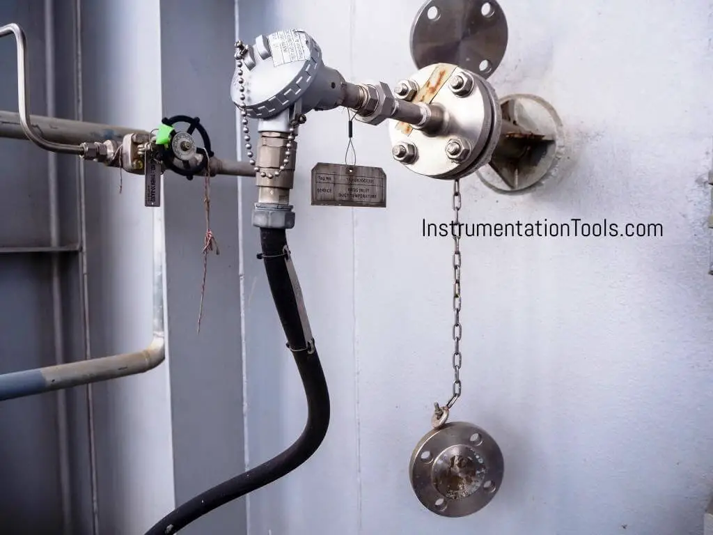
Here we shall see detailed specifications of Thermowells.

Contents
Thermowell SpecificationRead Next:

Thermowells shall be provided with every temperature element and shall be machined out of bar stock up to length 600mm and with SS 316 material as a minimum.

Thermowell Specification

Thermowell Installation

The design of thermowell shall be according to standard drawings for flange type up to 600# ANSI.

Above 600#, the contractor may use their proven design for a specific application

Flange material SS 316 as minimum

In corrosive and abrasive services Stallited thermowells are used.

There shall be no air gap between the bulb and thermowell to ensure a rapid response.

Internal diameter shall be suitable for temperature elements.

In very high-pressure applications, the welded type of thermowell is used.

The inside diameter of the finished thermowell shall be concentric with all other diameters with a tolerance of 0.2 mm.

The thermowell shall be machined and rifle drilled to a smooth finish after welding and heat treatment. The surface finish of the stem shall be 10-15u inch (0.254-0.381 microns).

Built-up thermowells shall be used in low pressure and low-velocity services like in fired heaters and also where thermowell immersion lengths greater than 600 mm is required. In all such cases, all-welded joints shall undergo 100% radiography testing. For joints where radiography is not possible, a dye penetration test may be carried out. Orifice dimensions and machining tolerances should be according to BS 1042 Part 1 standard.

Thermowells shall be assessed for resonance effects. Where Thermowells are installed in lines subjected to high fluid velocities (exceeding 6 m/s for liquids and 120 m/s for vapors/gases), combined stress and frequency calculation shall be carried out by a proven method. In case the thermowell design fails vibration analysis, an alternate design may be used by the contractor. All such designs along with calculations shall be submitted for the purchaser’s review.

Immersion Length `U’ of thermowells shall be as follows:

Thermowell Immersion Length

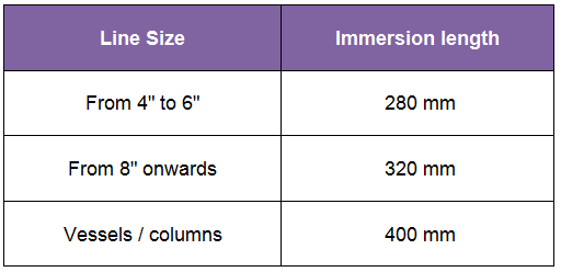
Immersion length is based on a 200 mm length between the flange face and the inner wall of the pipe. In special applications, where thermowell nozzle sizes are larger or where the temperature is to be measured at any specific location, the contractor shall decide the immersion length based on actual requirements.

Any pipeline less than 4″ nominal bore shall be blown to 4″ size to install thermowell.

Thermowells with lagging extension are used in pipe systems and on vessels, where these are insulated. The length of the lagging is determined by the thickness of the insulation. The standard lagging extension is 89 mm (3″) except for thermowells with an insertion length of 63.5 mm (2.5″), where the lagging extension is 60 mm (2″). Other lagging extensions are available on request with multiple of 89 mm (3″) to provide for standard instrument insertion length.

The thermowells are provided with 4 main methods of process connections: they are

  • Threads,
  • flanges,
  • weldings, and
  • clamp.

Threaded thermowells are the most commonly used wells, because of the low cost and the ease of installation.

Threaded thermowells are not recommended for pressure above 70 bar (1000 psi).

The standard thread sizes are 3/4″ and 1″ NPT.

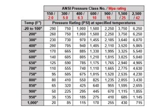
Flanged thermowells are used, when the pipe spec. calls for flange executions and at elevated pressure. The thermowells are supplied with flanges according to B 16.5 with raised face or ring type joint for pressure classes from 150 – 2500 lbs.

The flanged thermowell may either have the flange welded on the shank (stem), or the flange and shank may be forged as an integrated unit for use in severe service conditions.

Flange sizes are : 1″, 1 1/2″, and 2″.

Weld in thermowells are used at extreme pressure and temperature service conditions, and when ASME codes require welded connections.

The weld-in type thermowell is a low-cost item, but the disadvantage is that the well is not removable for inspection or replacement.

The standard weld in size is 38 mm (1 1/2″), 26.9 mm (3/4″ nominal pipe size), or 33.4 mm (1″ nominal pipe size).

Interest to add any further points? Share with us through below comments section.

Author: Kalpit Patel

Read Next:

  • Thermowell Insulation Thickness
  • Thermowell Installation
  • How to Select Thermowell?
  • Multiple Thermowell Installation
  • Temperature Sensor Accessories
Don't Miss Our Updates
Be the first to get exclusive content straight to your email.
We promise not to spam you. You can unsubscribe at any time.
Invalid email address
You've successfully subscribed !

Recommended Articles

Design and Implement Motor Control – Electrical Engineering
Installation Precautions of Thermocouple and RTD
What Temperature are Celsius and Fahrenheit Value Same ?
Air Consumption Calculation for ON/OFF Valves
Temperature Sensors Interview Questions
Radiation Pyrometer Working Principle
Share This Article
Facebook Whatsapp Whatsapp LinkedIn Copy Link
Share
Leave a Comment

Leave a Reply Cancel reply

Your email address will not be published. Required fields are marked *

Stay Connected

128.3kFollowersLike
69.1kFollowersFollow
208kSubscribersSubscribe
38kFollowersFollow

Categories

Recent Comments

  • William Snyder on Top Non-PLC Certification Courses for Automation Professionals
  • Kamli on Top Free PLC Software
  • Guifty Shimica on Top Non-PLC Certification Courses for Automation Professionals
  • Guifty Shimica on Top Non-PLC Certification Courses for Automation Professionals

Related Articles

Relationship between Temperature Scales

Relationship between Temperature Scales

Where should we terminate the shield and why

Where should we Terminate the Cable Shields ?

Diaphragm seal for pressure measurement device

When to use a Diaphragm Seal?

Control Valve Packing

Control Valve Packing

Control Loop

What is a Control Loop ?

RTD lead resistances Wiring

Resistance Temperature Detectors Working Principle

Thermocouple Material Characteristics

Thermocouple Construction

Peltier Effect

Peltier Effect Theory

More Articles

PID Controllers with output high select Logic

PID Controllers with Output High Select Logic

TON Timer in RSlogix

Why is RTO used in the Place of TON Timer?

PLC Tutorials - Timers and Counters

Difference between Timer and Counter – PLC Basics

HART Multidrop Network

What is HART Protocol ?

working-of-pnp-transistor

Working of NPN Transistor

Internet of Things (IOT)

History of Internet of Things (IOT)

Arc Fault Breaker (AFB) Electrical Problem Solved

Premature Arc Fault Breaker Failures

Automatic Liquid Mixing Application

PLC Program for Automatic Liquid Mixing Application

Follow US
All rights reserved. Reproduction in whole or in part without written permission is prohibited.
Welcome Back!

Sign in to your account

Username or Email Address
Password

Lost your password?