For a Thermocouple, Temperature should be measured with the cold junction at 0°C or 32°F (At thermocouple terminated side i.e. transmitter).
Meaning that we have to maintain 0°C or 32°F at temperature transmitter terminals which is practically not possible. so compensation is required to correct the measured temperature reading.
Cold Junction Compensation
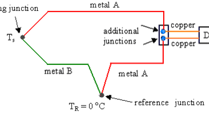
When a thermocouple or its extension wires are connected to the terminals of a device like a thermocouple transmitter the cold junction is at the room temperature T1°C.
If both temperatures of the hot and the cold junctions are above 0°C, the device receives a lower emf than when the cold junction temperature is 0°C.
In order to measure the temperature accurately, we need to add the emf value which corresponds to T1 to the measured emf. To add this emf is called cold junction compensation.

The figures show the temperature-emf curve (not to scale) and a temperature measuring setup with a thermocouple and a millivolt meter. Assume the cold and the hot junctions are at T1°C and T2°C, respectively.
According to the temperature-emf table of the standard, the thermocouple generates emf of E1 mV at the temperature T1 and E2 mV at T2. The millivolt meter receives the potential difference, E2 – E1 which corresponds to T2 – T1.
In order to obtain T2, we need to add E1 to the potential difference, E2 – E1 for elimination of E1.
 An actual example may better clarify the above discussion. Assume that we are using a Type E thermocouple to measure T2 (say process temperature), which is 550°C (1022°F). Now the another thermocouple junction T1 say which is terminated at temperature transmitter or in control room & T1 temperature is at room temperature which is 25°C (77°F)
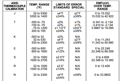
According to the temperature-emf table of Type E, the thermocouple generates (with reference to °C):
Process temperature (T2) is 550°C and so as per Type E thermocouple table or measured voltage is : 41. 045 mV at 550°C
Now room temperature (T1) is 25°C and so as per Type E thermocouple table or measured voltage is : 1.495 mV at 25°C
The potential difference is 39.550 mV.
The thermocouple type temperature transmitter displays the temperature value based on 39.55 mV which is equivalent to 531.5°C. But actual process temperature is 550°C, so there is 18.5°C error exists (Error=550-531.5).
This temperature error will be compensated using cold junction compensation technique.
In Cold junction compensation, we place a temperature sensor near the temperature transmitter terminals (if thermocouple terminated in field) or at control room terminations (if thermocouple terminated in control room) then this temperature sensor measures the room temperature T1 value say 1.495 mV @ 25°C.
Now this measured milli volt will be added to the already measured potential difference value i.e. 39.55 mV, so 39.55mV + 1.495mV = 41.045 mV, so temperature transmitter shows compensated corrected temperature reading.
Read Next:
- What is Indicator ?
- Thermocouple Errors
- Bi-metal Temperature Sensors
- Non-contact Temperature Sensors
- Instrument Technician Questions


Best one
While most modern temperature transmitters employ cold junction compensation, many problem with temperature reading errors are do to connections in the field extension wiring and terminals. You must use the same type of extension wire as the thermocouple being used and the terminals at junction boxes between the transmitter and the thermocouple sensor must be the same type metal as the extension wire.
Como se corregirá???, si la temperatura del medio ambiente es variantes en el tiempo, la compensación aquí mostrada es un caso ideal de ambiente a 25°C,
Creo que en mi caso propuesto, la compensación devera ser dinámica, como se lograría esto????
Translate from spanish :
As will be corrected, if the temperature of the environment is time-varying, the compensation shown here is an ideal case of ambient at 25 ° C,
I think in my proposed case, the compensation should be dynamic, how would this be achieved ????
Hi, It is dynamic compensation only as we are using extra temperature sensor for measuring the cold junction temperature. For this purpose we keep an temperature sensor near transmitter terminals.
English to Spanish :
Hola, Es compensación dinámica sólo como estamos utilizando sensor de temperatura adicional para medir la temperatura de unión fría. Para ello mantenemos un sensor de temperatura cerca de los terminales del transmisor.
Will there be error in measurement of temperature in R and S type thermocouples while using transmitter?
Since the curve is not linear at room temperature and at higher temperatures.
Hi, There will be no error in measurement and thermocouples have non-linear equations only.
What i meant was, say mV measured using R type T1 is 9.204 (900 degC) @ 25 Deg C. using temperature chart of R type temperature sensor (CJC) in Tx will give 0.14 mV at 25 degC . So total mV=9.204+0.14=9.344 mV. So temperature in Transmitter will be shown as 910 degC (9.344). While the actual temperature is 900 deg C+25 deg C = 925 deg C. While using thermocouple such as k type, which have linear graph doesnt have this error
Hi, There will be no error. And different thermocouples have different relations.
Hello sir
I have a doubt in my mind about the temperature sensors being used for compensation .my doubt is what type of temperature sensors should we use whether we should we use thermocouple or any other temperature sensor? if we use thermocouple only then don’t you think this thermocuple will also require Cold jn compensation where as if we use other temperature sensors then how can we nullify the error as thermocouple and other temperature sensor will not give same reading at that temperature .
Hi, Every temperature transmitter have inbuilt temp sensor for compensating the cold junction error.
Sir , what is the nature of the inbuilt temp transmitter (pt100, thermocouple , etc ) .
Hi sir
Very Good article.
Sir , which type of temp sensor is used at cold junction (transmitter ) side for CJC error ????
i hope there will be semiconductor based temperature sensor like LM35 IC etc… These sensors are most suitable to place inbuilt in a transmitter.
Good article
Thank you